
10 Element 2m VHF OWL Yagi
These days, the antenna world seems to be swamped by tidal waves of acronyms by designers and manufacturers temping potential buyers to part with their hard-earned cash. OWA-OWL-OPDES-LFA-LFAQ – the list seems endless, but many of the hams I chat too are seemingly confused by a world that’s inherited every conceivable abbreviation on the planet.
Looking through the many models around, some designs seem to have the upper edge. But there’s plenty to chew over whether it be more bandwidth, better gain, better front-to-back ratio, lower sidelobes. Its a hefty heavyweight and seemingly confusing environment for sure.
So, for the homebrew enthusiast we’ve tried to simplify things and have modelled a nice ‘OWL’ array for 2m [although no birds were physically involved or harmed in this experiment] – that we can guarantee!

It’s got great gain, bandwidth and nice side-lobe attenuation. We’ve designed it with a folded-dipole driven element [rather than a split-dipole] meaning it requires no matching as the natural impedance is around the 50 ohms point.
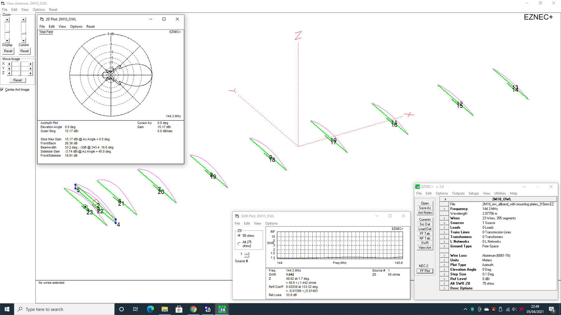
Just connect your coax up to the feed-point and away you go. Our EZNEC model also includes the element mounting brackets which actually doesn’t really mess up or change the design in any way – but they’re in the model just for reference.
Click on the images below for hi-res PDF’s of the modelling
Click here to download our EZNEC modelling file
You could design it with a single ‘Split-Dipole’ driver. Doing it this way makes the natural impedance of the array around 12.5 ohms. This could then be matched by using 2 x 50 Ohm coax lengths, both a quarter-wave length. These are connected in parallel and create a 1:4 upwards transformer [12.5 to 50 ohms]. You need to take into account the velocity factor of the coax. Essentially, make 2 quarter-wave stubs and connect them in parallel. DK7ZB shows you in more detail how to make one, but it’s a pretty easy affair for sure.

I’ve built a handful of these and they work very well. I’ve used [in typical ‘Vortex‘ style] some nice HD hardware. In essence – this baby will probably withstand a 150mph++ environment with its 9.5mm solid rod aluminium elements [apart from the driver] and 1/4 inch mounting plates with genuine ‘Stauff’ clamps. What we would say is that this is NOT a flimsy lightweight design and could cost well over £200 in parts, although many constructors may well have some items already in their workshops thus reducing the outlay.
We’re pretty sure you’re an ingenious bunch out there and some people I know could probably make it for £20. As always – you’re the constructor so it’s your call.
Construction Data
1 x 5m section 1.25inch x 1.25inch x 10 gauge aluminium box
1 x 1m section 1.25inch x 1.25inch x 10 gauge aluminium box
1 x 1m section 25mm x 25mm aluminium bar [cut into 3 sections] for 3 x spliced boom inserts.
As a minimum, you could however get away with 1 splice. Use a full length 5m boom which would be spliced to the small 1 meter end section [your choice]
11 x 6.35mm [1/4inch] plates to mount elements
18 x M8 U-Bolts [x 1.25 inch] – Check out U-Bolts R Us here
22 x 109.5A PP Stauff Group 1A Polypropylene clamp halves.
44 x M6 x 35 Socket Head Bolts, M6 Nyloc Nuts and Washers
4 x M8 x 60 Hex Head Bolts, M8 Nyloc Nuts and Washers
3 x 5m lengths of 3/8ths diameter aluminium solid rod
1 x 2m length of 12mm x 2mm wall aluminium tube
Suitable fibreglass insert or hombrew insulator for the dipole center
2 x 50cms length of 5/16ths tube [any wall size]
M5 Socket Button Bolts for the feeder pins
The feeder socket and any mounting solution is left up to the constructor
Construction Images
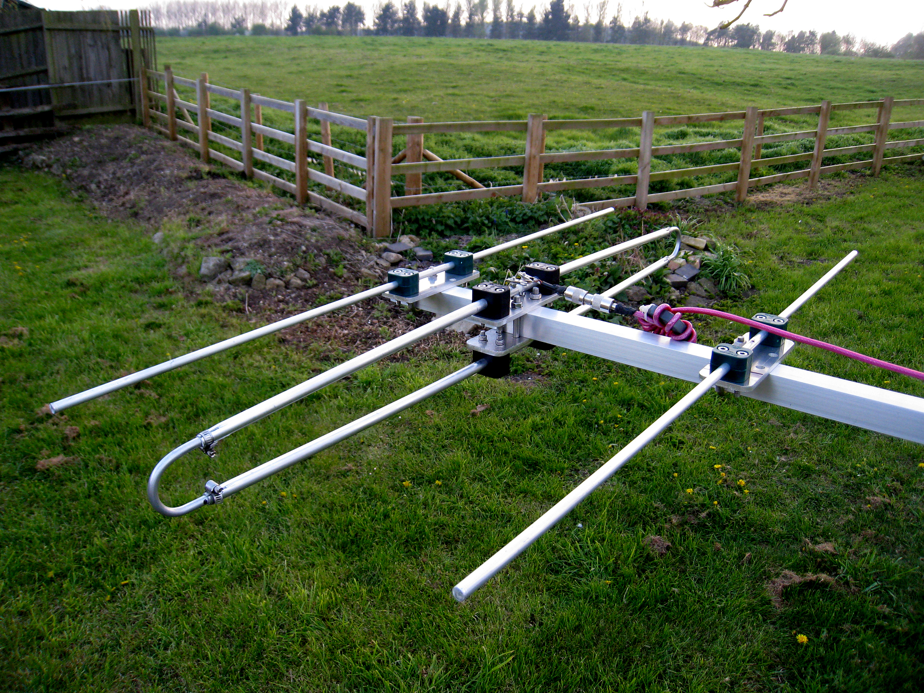
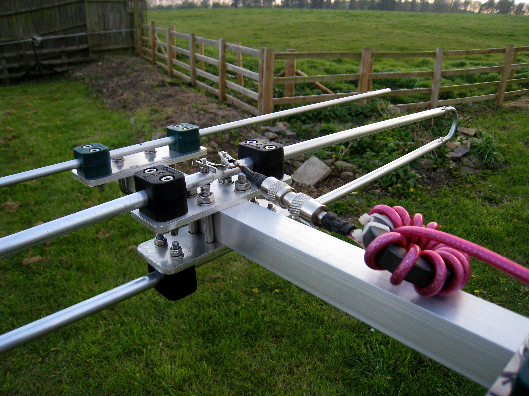
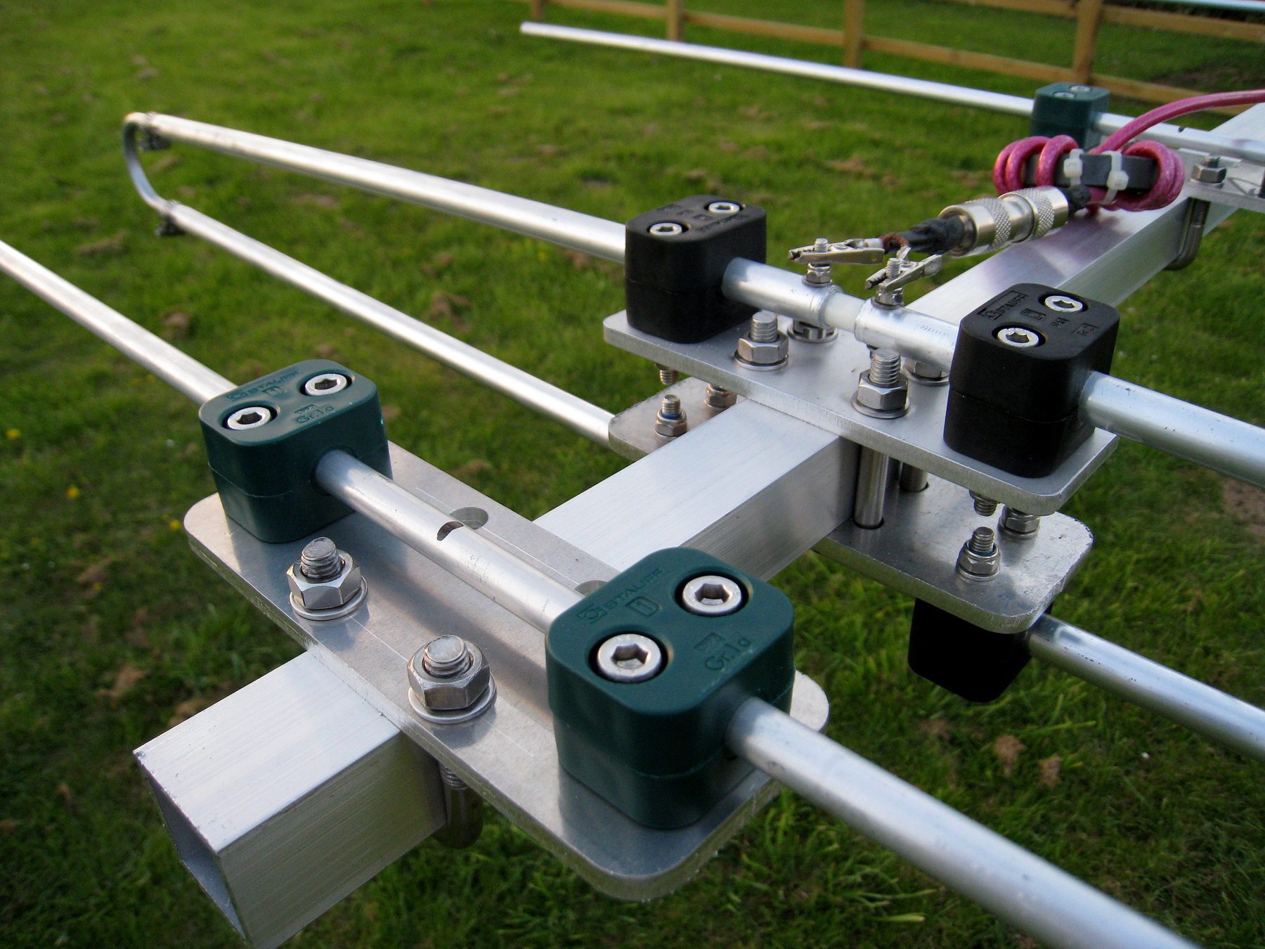
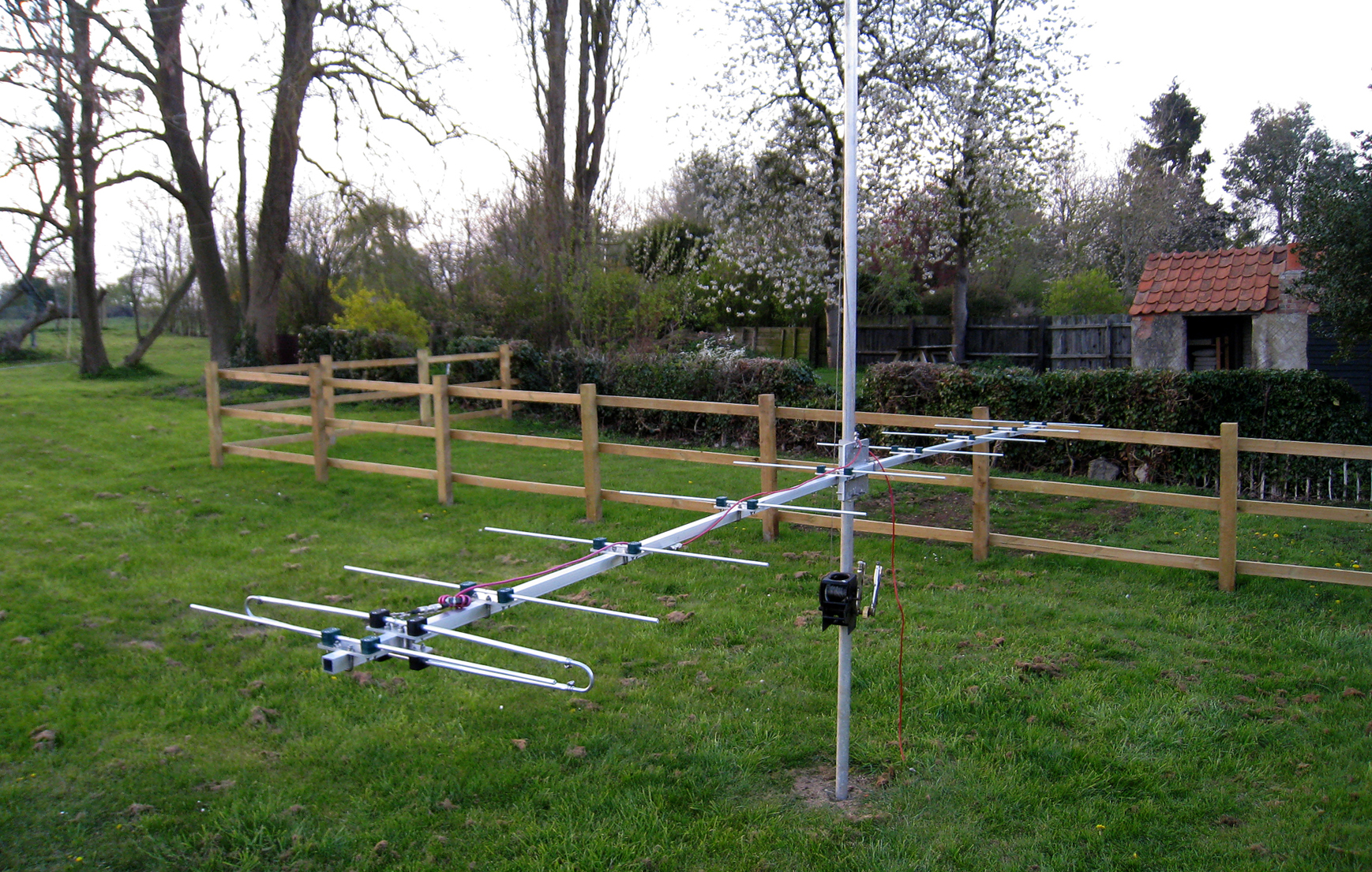
The above images were taken during initial construction and testing. As you can see, no feed socket was connected at the time so a small allowance will need to be made, whichever connector you decide to use. We’d suggest a premium ‘N’ Type socket from a supplier such as ‘Sinequanon’. Here’s some great ‘Rosenberger‘ chassis sockets.
The balun on the feed is a Type 61 ferrite core [built for 10m] and is not really designed for 2m VHF. It has too many turns although choking impedance was over 2k so was useful just for test purposes. We’d suggest constructors use 3-4 turns of premium grade coax on a 1 inch former to create a useful feed point RF choke.
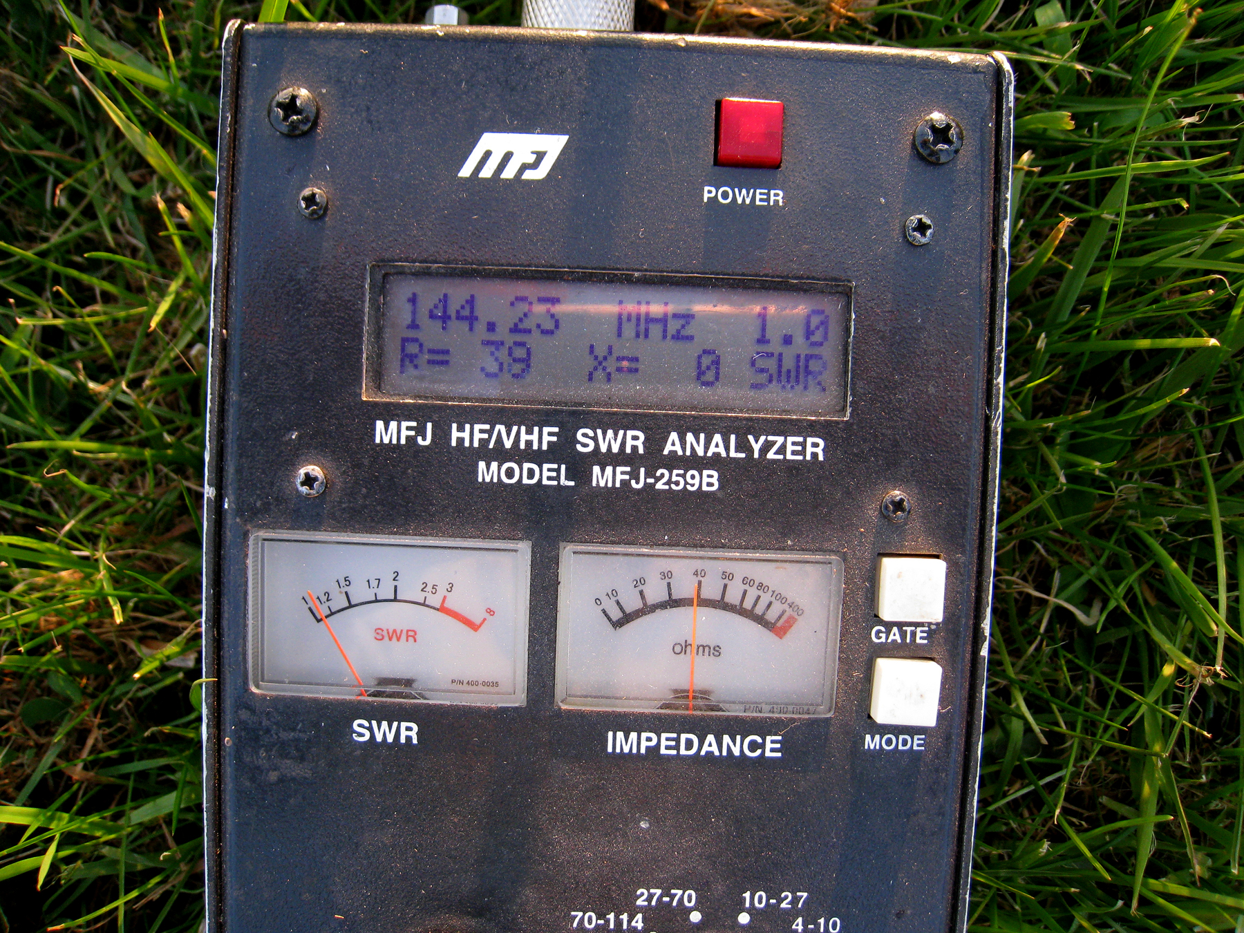
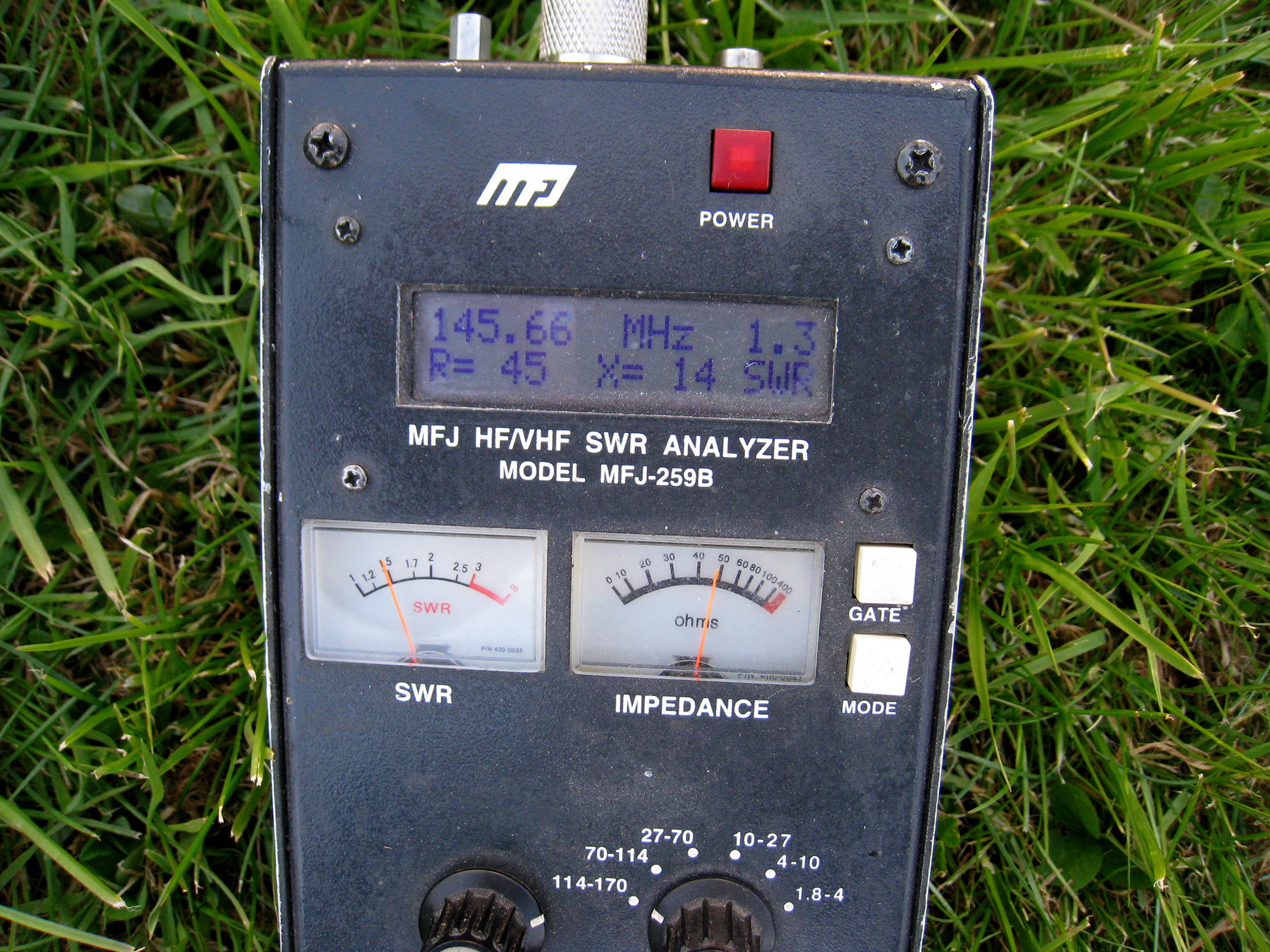
As you can see, bandwidth is great. We set this particular antenna’s resonant point at 144.300MHz, so at the SSB/CW end of the band. The SWR remained at 1.0:1 well down into 143MHz. The test height of the antenna giving the above results was 1 wave-length [2m] above ground [Grass].
Constructors could potentially set the ‘Sweet-Spot’ a little higher [say around 144.700MHz]. This will improve the high-end at 145.600MHz bringing it down to 1:1 to 1 with little change at 144.300MHz. As constructors – it’s your shout!
This antenna is currently in use at G3XFA, G1IZQ and M0NKL

