
A 5 Element 28 Ohm Yagi for 2m
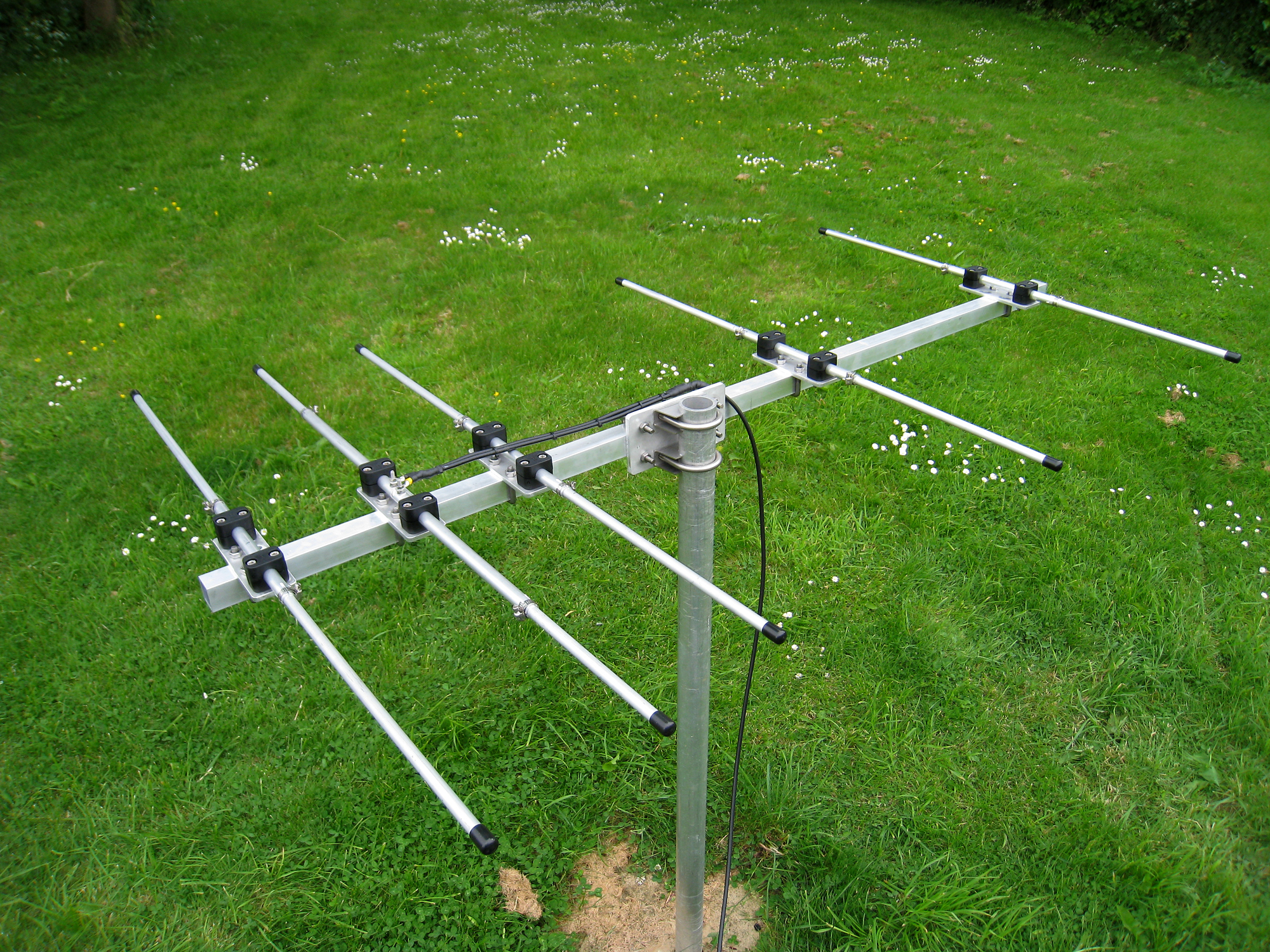
Here’s a simple 2m antenna project that can be used for either 2m FM/Repeater work [by using it vertically polarized] or for 2m SSB/CW work in the horizontal polarity. The image below show a development antenna made a couple of years ago set up as a horizontal antenna.
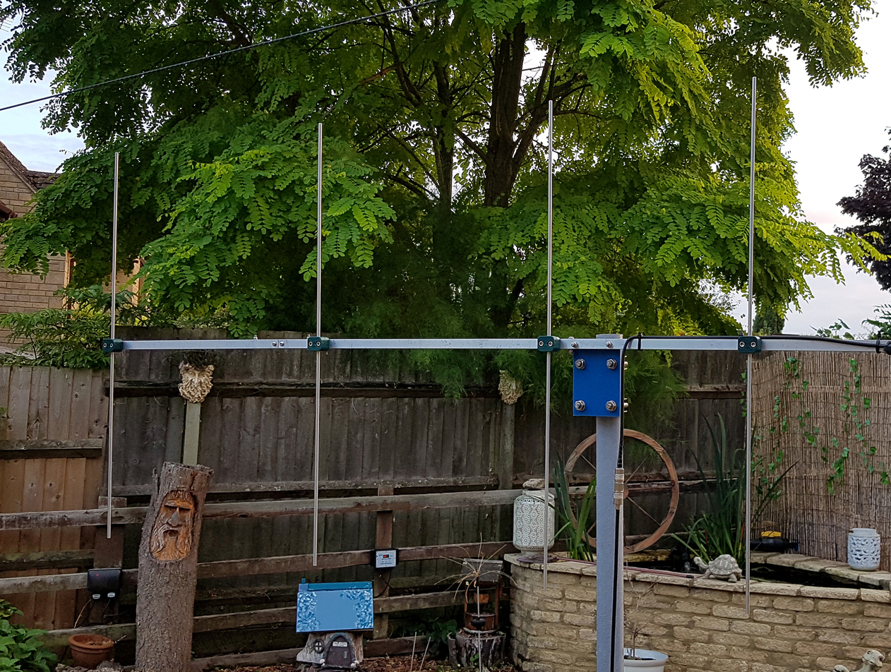
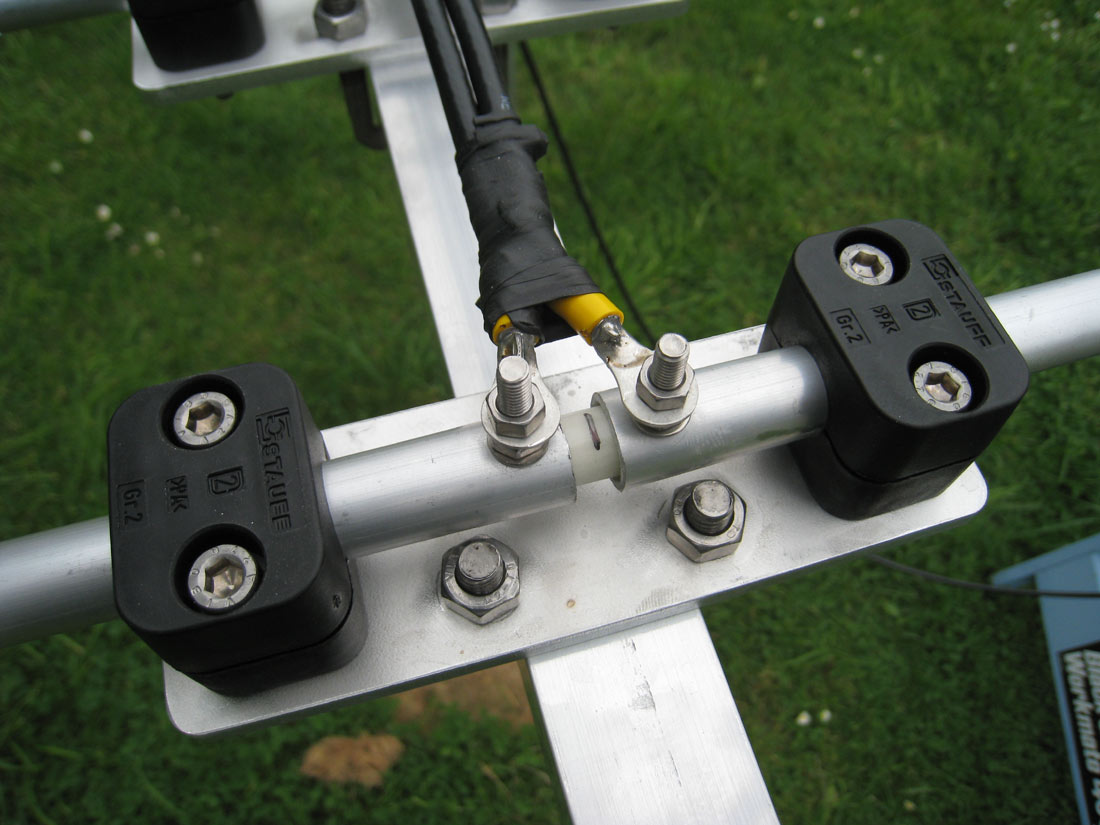
We’d suggest however, that you construct the boom and mountings similar to this design – rather than using 16 and 12mm tubes. It also removes the need to use U-Bolts for the element mounting plates. It’s easier and more cost effective [see image below].
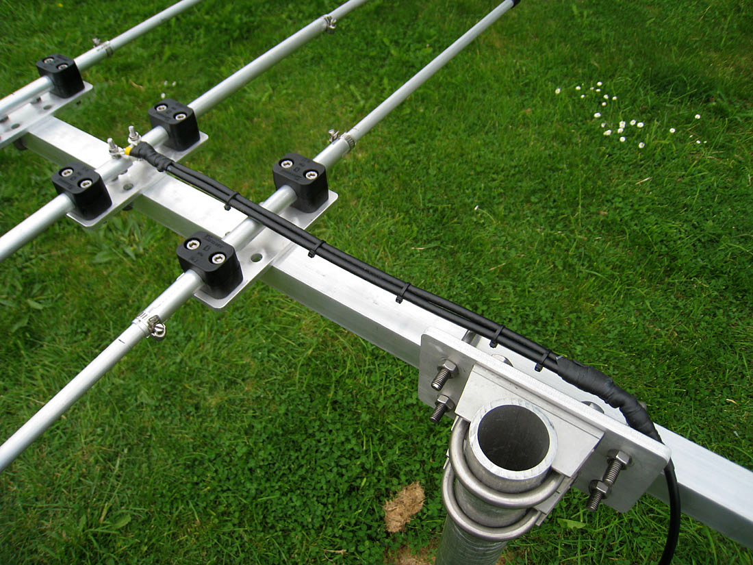
The heart of the design is a 5 element Yagi with a natural impedance of 28 ohms. In this design we match the very flat 28-ohm impedance to 50 ohms by employing a ‘DK7ZB Match’ [coaxial transformer] which comprises of 2 equal lengths of 75 ohms coax at the feed point as a matching stub – more detail on this later.
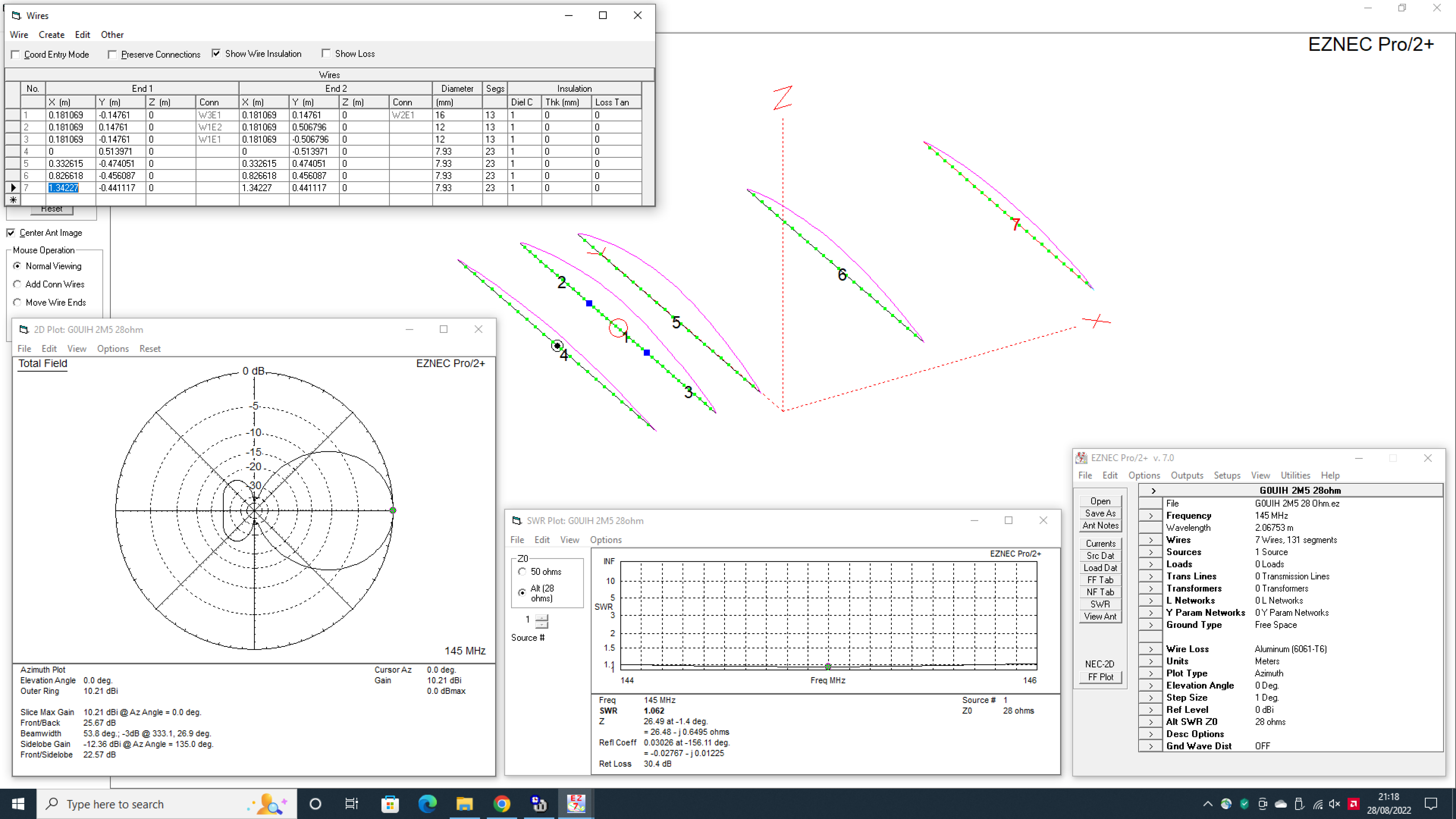
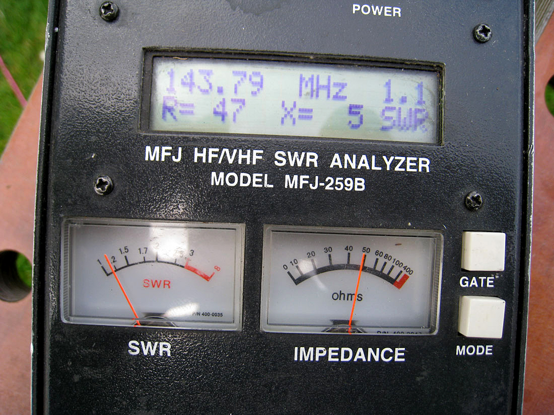
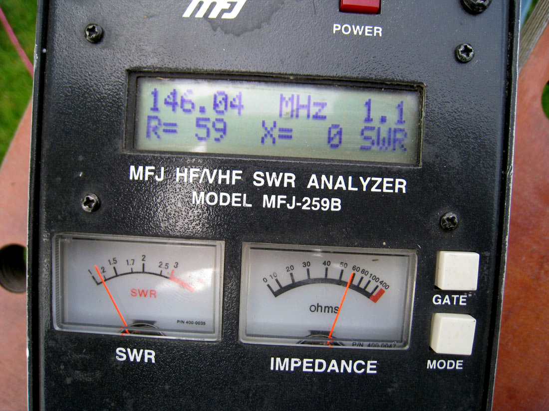
The result is an antenna with a pretty near flat SWR from 144 to 146Mhz. We’ve chosen 16 and 12mm tubes for the driven element and 7.93 mm [5/16ths] aluminium rod for all parasitic elements.
You can use a different diameter tubes for the driver, but we found this gives the user a model that is easily adjustable. The 7.93 mm [5/16ths] rods are also solid enough to not bend if dropped [within reason]. All-in-all, it’s a pretty sturdy affair but very lightweight.
Although the included images show the antenna built purely of 12 and 16mm tubes, we felt the revised tube and rod sizes created a better-looking and easier/cheaper array.
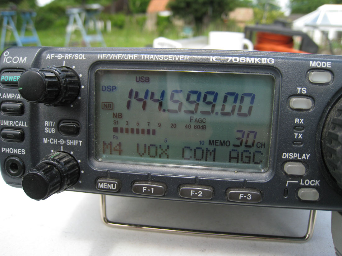
The antenna gives a very nice clean pattern with forward gain of over 10.2dBi and a front to back exceeding 25db [at 145MHz]. Bandwidth is exceptional and we’d be surprised if your analyser moved very much between 144 and 146MHz making it very wide banded.
We’d note that if users decide to operate this as a vertical beam, then a section of non-conductive material should be used as the support from the boom. You don’t need much [only a couple of feet or so], but this removes any possible interaction between the vertical antenna elements and the vertical supporting mast.
If you use this as a horizontal antenna, then a [normal] metallic [or any other] type of pole/support can be used without any affect on the antenna’s radiation pattern.
The 28 to 50 ohms DK7ZB matching harness can be made out of any 75-ohm coax. A particular favourite is satellite TV cable. Currently most Sky installers use ‘Webro WF65’ which will do a fine job with power levels up to about 400w. It’s easy to come by and relatively cheap.
The matching harness is actually 2 x ¼ wave sections of coax laid next to each other. If you use the ‘Webro WF65’ coax then you can use the measurements here. Likewise, in the images here, we’ve used a slightly heavier duty coax [Webro WF100] – this will handle about 750w and the 2 x ¼ wave lengths are the same [2 x 45cms].
The data spec for both types of coax is nearly identical and of course they are manufactured by the same company.
Here’s a PDF of how to ‘wire’ up the match using your 2 sections of 75-ohm coax
If you use any other stock, then you [may] need an antenna analyser to trim the stubs to their correct lengths as the velocity factor of the coax should be taken into account. We’ve done the maths for you if you use WF65 or WF100 stock.
If you don’t have an analyser, then a ‘trial and error’ figure of 0.81 [velocity factor] seems to come fairly close with the majority of manufacturers.
Use 2 sections of coax both 45 cms end-to-end [including tails]. Tape them together as one parallel lead. See the DK7ZB image on how to make the harness, but in essence, tie the braids together on each side, then tie the inner coax cores together [again at each end]. On the far end, connect the braid to one side of the dipole centre and the inner core to the other side.
At the other [shack] end, solder the braid to the braid on your 50-ohm main feeder and the centre core to your centre core of your 50-ohm feeder from the shack. As always at VHF – use the best quality 50 ohm coax that you can afford to ensure the lowest losses.
Finally, solder all joins and secure all with ‘Hodgson Flexistrip Butyl Tape’
It’s not quite as cheap these days, but you can still get a 19m roll for just over £6.00 [price correct as of August 2022] and is much cheaper than the highly overpriced ‘Coaxseal’ from the USA.
For EZNEC and antenna modelling enthusiasts, the EZNEC file for this project can be downloaded here.
GETTING STOCK:
- 5/8ths [16mm] x 1.65mm wall Aluminium Tube: Aluminium Warehouse
- 12mm x 2mm wall Aluminium Tube: Aluminium Warehouse
- 8mm [5/16ths] Aluminium Rod: Aluminium Warehouse
- Stauff Polypropylene Clamps. All Group 1A sizes are available here
[Use the Green ‘Polypropylene’ ones] - Boom: 2.5m x 3/4″ x 3/4″ square section x 10 gauge – Aluminium Warehouse
- Driver Mounting Plate:
Any 1/4 inch ally plate [but you could use anything that’s handy] - A couple of ‘Jubilee’ style or small hose clamps that fit a 16mm tube
- M6 Stainless hardware [nuts/bolts/washers etc]
- Exhaust Clamps and Saddles [x2] – to suit your own mounting solution and pole size
ELEMENT LENGTH DATA: [Actual Build – Exposed Lengths]
- Reflector: 1028mm total [5/16 inch/8mm aluminium rod]
- Driver: Split Dipole 147.5mm each side of 16mm [5/8ths] tube
Use a small spacer to separate, such as fibreglass – then *359mm outer of 12mm rod [each side] - D1: 948mm total [5/16 inch/8mm aluminium rod]
- D2: 912mm total [5/16 inch/8mm aluminium rod]
- D3: 882mm total [5/16 inch/8mm aluminium rod]
* These are exposed lengths. Cut longer to allow for adjustment.
ELEMENT SPACING DATA:
- Reflector: 0mm
- Driver: 181mm
- Director D1: 332mm
- Director D2: 826mm
- Director D3: 1034mm
Enjoy your project as always.
73 – Steve G0UIH – q82.uk

