
How to Wide-Band a 3-Element Yagi
From time to time, it’s nice to have a directional antenna that covers most or all of the band you are operating on. Bands such as 17m are very narrow band, so there is little point in designing an antenna with a good bandwidth – it’s best to design purely with performance in mind. With a computerized model, that will give you in region of 7.9dbi forward gain and over 25db front to back. Rear side lobes are also pretty well suppressed. You can see what a plot looks like below.
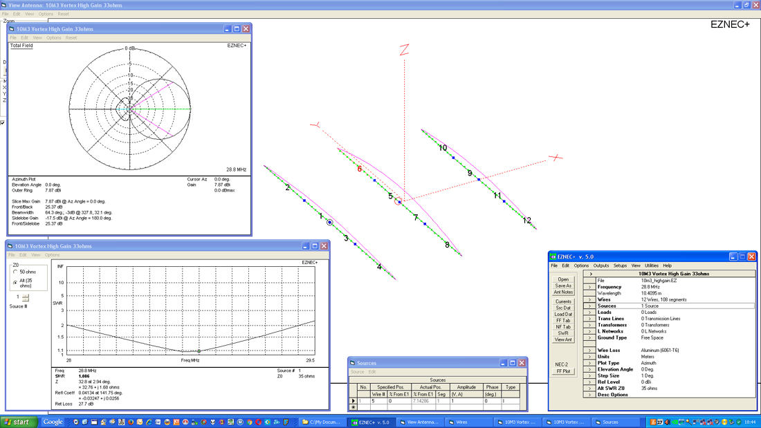
This is a 10m band high gain version which has a 2 to 1 SWR bandwidth of around 1400khz running from 28.000MHz to 29.400MHz. That’s pretty good in most cases, but the 1.5 to 1 SWR edges only give a bandwidth of 850KHz from 28.300Mhz to 29.150Mhz making it in reality quite narrow banded.
As soon as the SWR moves above 1.5 to 1, many of today’s modern transceivers will start to complain of a mismatch and begin shutting down, lowering the power output. Of course an external ATU will help the situation but you can design your antenna to be a little more forgiving especially on bands with a wider bandwidth.
So, how do we get our antenna to tune over a wider bandwidth? Let’s take our 3 element Yagi. We are not going to change anything regarding the length of the boom, it’s a reasonably long boom at 3.4m in length, but by moving the driven element forward by 30cms (typical for the 10m band – other bands will differ) towards the director and retuning the reflector element (adding 5 cms on each side) and then a minor adjustment on the driven element (+2 cms on each side), we have an antenna with nice gain (albeit slightly lower than the high-gain version), but with great front to back which covers a bandwidth of over 2.0MHz.
The 2 to 1 SWR limits are now 27.500MHz up to 29.600MHz – that’s 2.1MHz. The usable 1.5 to 1 SWR limits (so you don’t have to use an ATU) are now 28.000MHz to 29.300MHz- that’s 1.3MHz which is great for the CW and SSB portion of the band. If you are an avid 10m FM operator you could even re-tune the driver (take 3cms off each side) which would give you the SSB section and the 10m FM section. In either case, the whole band is covered with an SWR of under 2 to 1.
There is a minor caveat in that by making the antenna wide-banded in that you will give up a [very] small amount of forward gain – but we’re taking about .5db. It’s a small price to pay for that extra coverage.
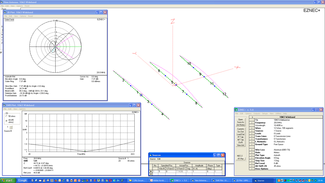
The antenna is presumed to be matched with a hairpin match and the natural impedance of the high gain version is around 33 ohms and the wide-banded model 45 ohms.
One other way to get more bandwidth is to apply the ‘OWA’ (Optimized Wideband Antenna) design which includes an extra element to the array. Adding an extra element close to the driver and in front of it helps to be an impedance controller of the whole array. With the correct design you can build an antenna with a bandwidth exceeding the normal Yagi ‘Wideband’ design by quite a margin.
To give you an idea of the SWR, here’s a run-down of an antenna we built for an 11m operator who was also a ham. He wanted to operate on both 10 and 11m. So we built him a 6 element Yagi that has great gain (over 11dbi) and over 20db front to back and an SWR that barely moves from 26.500MHz all the way to 28.500MHz – that’s a great 2.0Mhz bandwidth of below 1.3 to 1. The only downside is that there is a small reduction in forward gain when comparing to a standard Yagi design.
So as you can see, there’s more than one way to crack a nut and there’s no ‘right’ or ‘wrong’ way in antenna design – just different methods. Of course a good PC antenna simulation program (such as EZNEC or MMANA-GAL) is a must as you don’t want to just build your own design testing it by trial and error.
Computer designs are really the only way to guarantee a design will perform as close to what has been modelled.
Download the 10M3 [3 element Yagi for 10m] EZNEC file here

