
An End-Fed 160-10m Long Wire Antenna with a QRO 9:1 Un-un and 1:1 RF Choke Balun
So you’ve decided to homebrew an end-fed ‘Multi-band Sloper‘ antenna that will get you on the air from 160-10m. With a reasonably good ATU in the shack, you’ll achieve this and it won’t cost an arm and leg. And you can feed it with coax from your shack. It may also work on 6m as well.
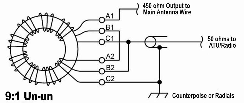
Here’s a nice homebrew project that would also suit constructors wanting to build a 9:1 Un-un [Unbalanced to Unbalanced] transformer. The heart of the Un-un uses a Type 43 [FT240-43] core and consists of a trifilar [3 wire] winding arrangement around the core. The wires are wound to create a 9:1 transformer and would ideally suit an end-fed long wire antenna fed against ideally – a good counterpoise, or a good radial system. Both will do a good job. But before you read on further, click on this link.
It downloads a very useful info sheet from ‘Balun Designs‘ in the US [we hope they don’t mind us mentioning them and giving them a plug 🙂 ]. It explains in excellent detail on the lengths to use when constructing a long -wire end-fed antenna and mega useful tips on how to feed it against a counterpoise raised about a foot off the ground – which they highly recommend as the ‘best’ solution. As an alternative solution, the ground wire can be just that. Connected to a ground radial system although Balun Designs see this is as not the optimum solution – although it works.
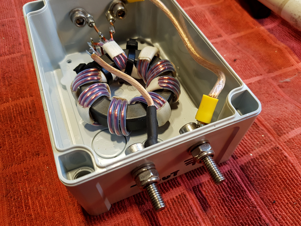
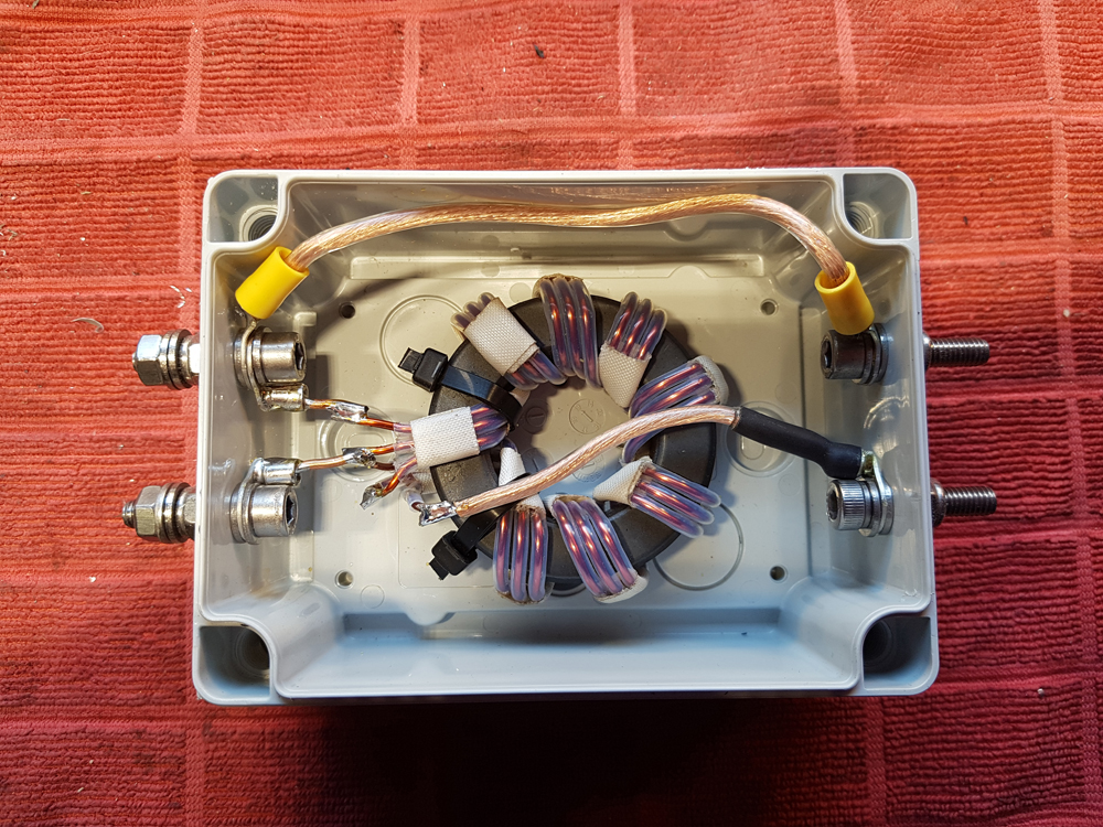
In construction, I use some hefty 14AWG enamelled wire which is additionally insulated using thin-wall Teflon [PTFE] tubing. The core should handle 2Kw and the design and construction used is very similar to that used by Balun Designs in the USA
Below is an image of the completed Un-un. In this set up, the input to the system is actually two M6 stainless steel pins. These are coupled to an additional 1 to 1 current balun which acts as an RF choke. Some may think the RF choke is not needed. It would certainly be the case if you had a very good RF ground. We’ll presume for this exercise that the grounding is sub ‘Good’ or we are using a counterpoise. system. Also it must be mentioned, the 9:1 Un-un makes a particularly bad RF choke as it’s really only an impedance transformer.
Remember, this isolates the coax back to shack [a good thing] – preventing feed-line and common-mode currents.
What should be noted is that because I’m fitting what is effectively an RF choke [the 1:1 balun], then the coax run back to the shack WON’T act as part of the counterpoise as its isolated. As I’m rather a purist, I believe that the counterpoise should be part of the antenna and therefore the feedline [as its coax] should be isolated from the whole affair and should not join the party. For starters, you don’t get any feedline radiation or common mode currents.
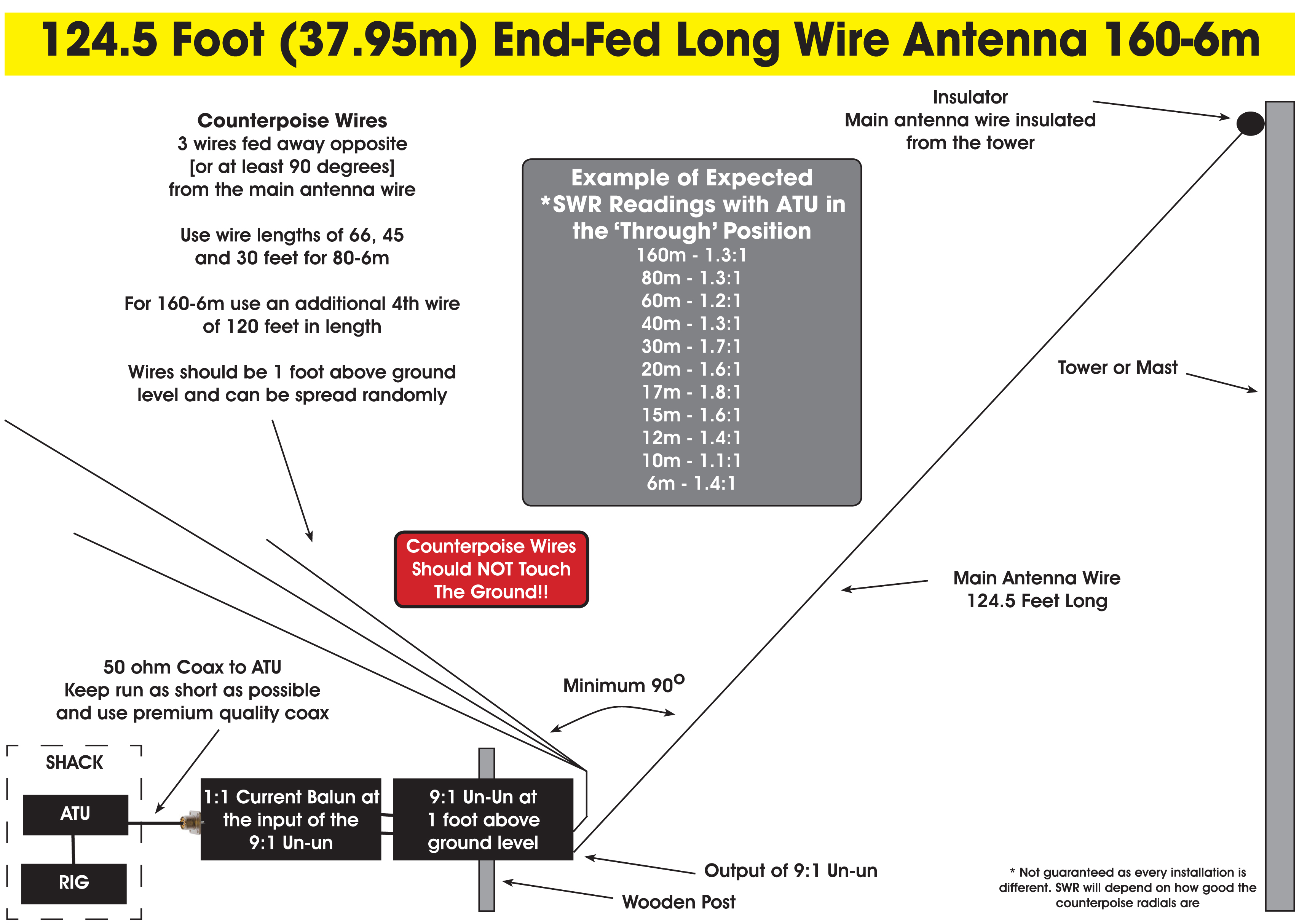
Important: The 9:1 Un-un does not have ANY properties in preventing common-mode feedline radiation. The included ‘Ferromagnetics’ balun DOES, and has enough choking impedance at the frequencies we are using to make an excellent RF choke. In essence, the counterpoise should be a totally separate wire [or bunch of various length wires] from say 35 to 120 feet.
To get you going, try three counterpoise wires. 66 foot, 45 foot and 30 foot. Connect them all to the ‘Earth’ terminal on the output of the 9:1 Unun and feed them in the opposite direction [or least at 90 degrees] to the main ‘Sloping’ wire. The counterpoise wires should NOT touch the ground. Ideally, mount them about a foot above the ground. With this recommended application and setup, your 9:1 Un-un should do you well with your long wire.
For the box, I’m using a trusted RS Components ‘Fibox’ box. These ABS boxes come in about a million different sizes and make great project boxes. As an additional bonus, they are ‘IP67’ rated, meaning they are good for most outdoor weather conditions with the lid being sealed. I would say as a caveat, I think it’s best to add a couple a small [M4] breather holes in the base of the box. This prevents moisture build up and, if by any chance the box does start to fill with water – then there’s an escape hatch so all your handy work isn’t ruined.
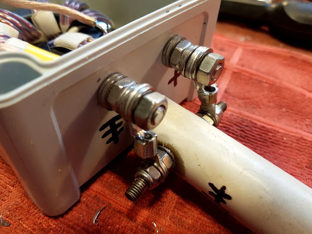
Remember to keep earth to earth and main feed to main feed – don’t get them crossed over!
So let’s take a closer look at the 1 to 1 balun. It’s actually an older commercial unit from UK company ‘Ferromagnetics’ and I think has type 43 cores. I can’t be a 100% sure on the core material as they ceased trading over 25 years ago and there’s no online info. Saying that, I’ve used this unit successfully in the past as a 1 to 1 choke on an 80 and 40m dipole. With all that said, you could use any good quality 1:1 Current balun as you obtain the same end result. If you want to construct your own – see our article on Q82.uk here.
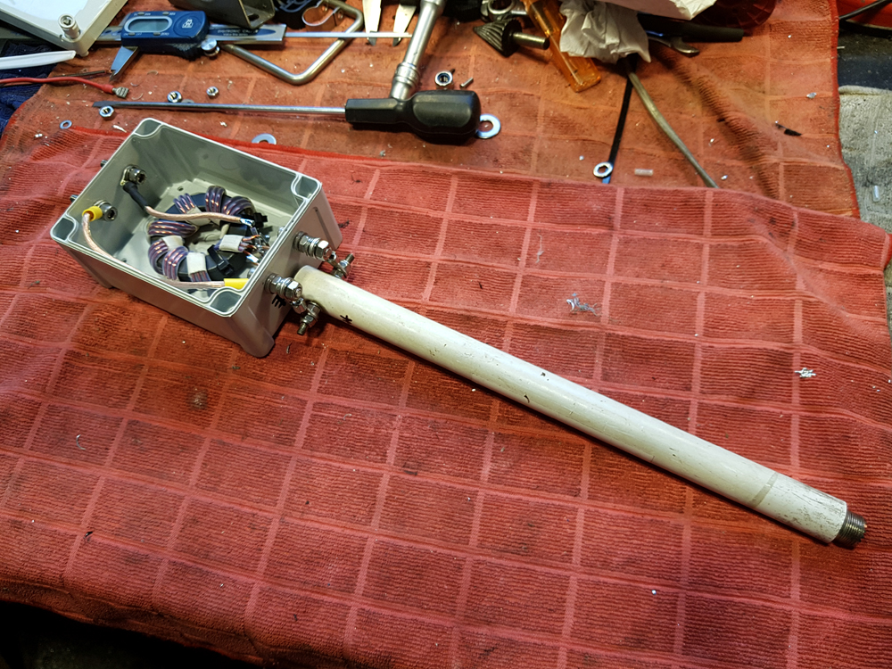
The cores used are the smaller cylindrical cores which are all strung out in a 12-inch tube. The input of the choke is an SO239 socket, which means the constructor can feed their unbalanced coax to this point and then feed it back directly to the shack – so about as straightforward as you can get.
So, with this system, you have an excellent RF choke [the 1 to 1 current balun] which is then fed to the 9:1 transformer.
On an analyser, the Ferromagnetics choke shows a nice flat response from 1.5 to 30 MHZ and only rising to 1 to 1.2 on 6m which seems to suggest a wide-banded core material. However, see my notes about operating above 30Mhz below.
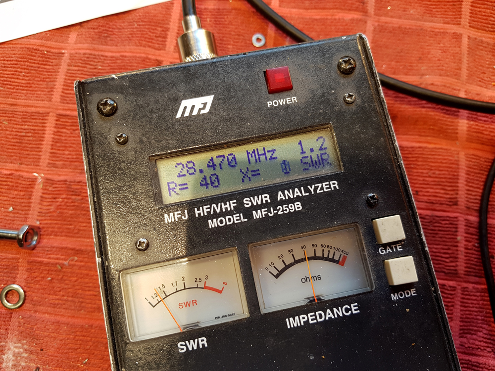
There is a caveat with operating above 30Mhz. In constructing the Un-un, ease of construction was the first criteria – as such, the link wire ‘C2‘ is somewhat long. In subsequent testing and running the system through an analyser, the SWR on 6m rose quite considerably although it was useable with a good ATU. Saying that, 6m would not be considered a ‘prime‘ band for this antenna as there are much better solutions for the 6m band.
In summary, when using a type 43 core for the 9:1 Un-un, you can expect SWR reading similar or in the region of those listed in the above article which is based on the load being 450 ohms resistive. Of course, one must realise that the impedance of the antenna will vary with frequency. I chose 450 ohms as the sweet spot. You may find that in actual use, some bands have higher or lower impedances than 450 ohms and as such a 9 to 1 impedance transformer may not suit every band for all occasions. It’s a ‘try, see and evaluate’ solution for sure – but as mentioned earlier, a good ATU in the shack may help you achieve a good match across many, if not all the HF bands.

