
A large 80m-2m Multiband Delta Loop.
An in-depth look into its performance with modelling and various feeder location options.
There’s plenty of online data regarding Delta Loops, unfortunately much of it gives the builder a less than accurate picture on what to expect regarding performance. At Vortex, we’d been building delta loops for years. We’ve fell into a multitude of swamps and quagmires – I’ve learnt the hard way. Unfortunately, many good willed projects fail – so we’ll hopefully put that right for the budding builder.
Deltas can be either horizontally or vertically polarised and the constructor has two options when orienting the loop. Either as an ‘Apex Up’ scenario which is a fairly common arrangement as a tower can be used to support the apex of the loop, or ‘Apex Down’ which suits 20m and higher band loops made mainly from aluminium tubing and a horizontal top-wire.
Occasionally the constructor may decide to use the apex down route when they have the use of tall trees or structures which can be used to support the two corners of the top horizontal wire.
Here, we’ll follow the ‘Apex Up’ route as we plan to use the tower to support the apex of a wire loop and subsequently feed the loop either on the side, at any lower corner or on the horizontal base wire. The horizontal base wire of the loop is about 2m above ground. The loop has three wires, 27m on each leg. The modelling reflects this although the builder could stray from the ‘equilateral triangle’ shape to some degree by having a longer base wire and shorter vertical wires.
One area certainly worth a read is from the superb ‘Low Band Antenna Book‘ by John Devoldere ON4UN which examines in detail various scenarios, especially when changing the feed position. We’ll initially base the following observations on the fundamental lowest frequency of the loop, in this case 3.750MHz.
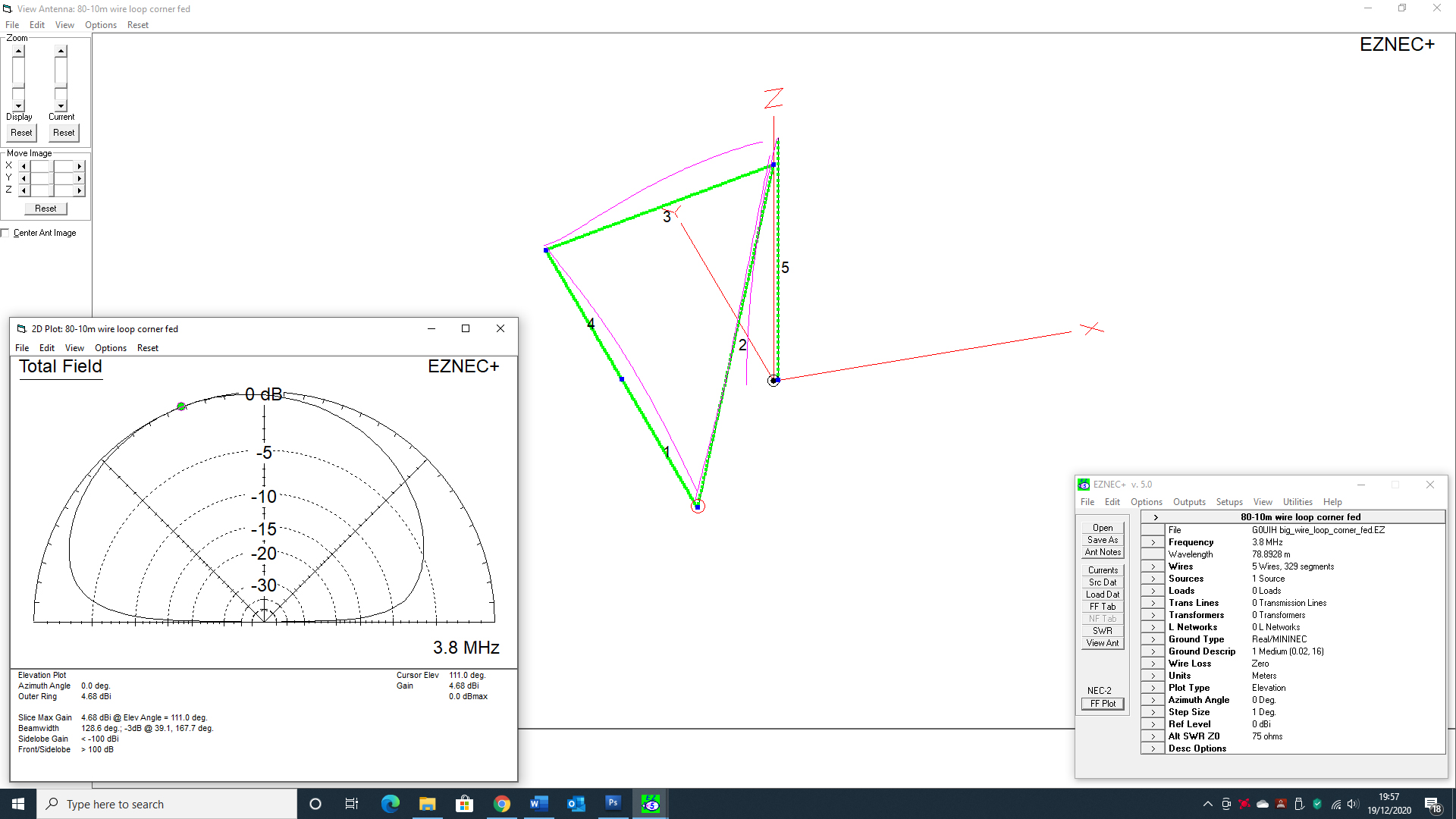
When a delta loop is horizontally polarised [Apex at the top] and fed at a bottom corner we see in modelling, improper cancellation of radiation from the horizontal wire. This produces a strong high-angle horizontally polarised RF component. High angles generally mean poor DX performance. Our own model showed good gain [4.68dbi] but with a high take-off angle of 65 degrees.
The main reason for this is that any horizontal antenna is affected by its height above ground. The horizontal delta on 80m is effectively being operated at a lower than optimum height above ground.
Compare these results against the scenario when the antenna is being fed 0.08 of a wave-length [6.3m] up the side of the loop as shown below. The change in feed arrangement [the feed point is the small red circle] alters the polarity to ‘Vertical’. The same antenna in the vertical polarity model showed similar gain [4.27dbi] but with a much lower take-off angle [only 23 degrees] – making it an excellent DX antenna.

Modelling the antenna further, we run plots on other bands with the same feed arrangement – corner fed [horizontal] and side-fed [vertical].
A pattern begins to emerge. Generally, the horizontal delta loop doesn’t like being operated at a less than optimum height giving high-angle lobes. OK, on some bands the angle of radiation is acceptable [40, 15 and 12m for instance] but on others [80, 30, 20, 17 and 10m] – the results are not that convincing for the prospective builder.
Take the side-fed vertical polarity loop. It should be a great DX antenna on 80, 40, 30, 17 and 10m. Even on less than optimum bands [20, 15 and 12m] the performance should be more than adequate.
As a caveat, we also performed a model by feeding the loop at the mid-point of the horizontal base wire. Here we found some interesting results. Gain on some bands was incredible.
On 80m based on average ground at the modelled working height [apex at 18m and the base horizontal wire at 2m above ground]. The 80m gain was a super impressive 8.42dbi. This would give the user a really hefty 80m signal for sure.
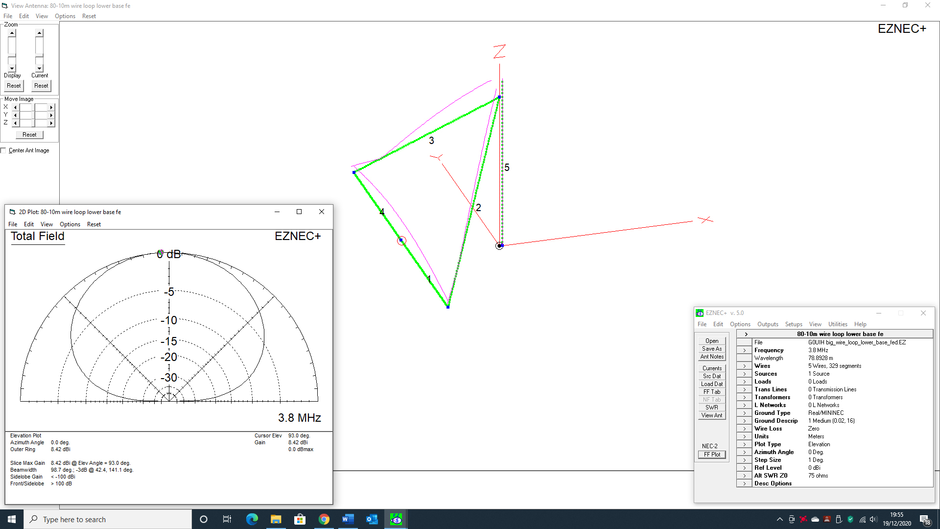
But as we all know, there’s no such thing as a free lunch and the trade off is that it’s a real ‘Cloud-warmer’ antenna with a take-angle of 87 degrees. In essence, all your RF is going straight upwards so you’d be super loud around the UK and to some degree into EU, but on DX – well you’d have to try it out as on paper, it’s shouldn’t be that good.
Saying that, we’ve read many reports of so called ‘High-Angle Cloud Warmer’ loops performing excellently as great DX antennas. So, there’s no right or wrong. It’s really down to each constructor to experiment and evaluate the overall scenario.
As a summary – if you are NOT a DX buff and just love to chat around the UK or your local country/continent, then the horizontally polarised loop fed in the centre of the base/lower horizontal wire looks to be a great choice. Where else can you get these superb high gain figures [8.42dbi on 80m for example].
Heres’ some links to download the PDF’s of our findings. You can download three separate PDF’s all with different feed point locations [2 horizontal and 1 vertical]. With each feed point we’ve analysed the performance using EZNEC on all bands from 80-2m.
Download: 80-2m Delta Loop – Horizontal Polarisation – Lower Corner Feed
Download: 80-2m Delta Loop – Horizontal Polarisation – Center Lower Horizontal Wire Feed
Download: 80-2m Delta Loop – Vertical Polarisation – Fed on the side leg
See how to feed your Delta Loop [click on image below] and we show you how to connect a 4to1 balun transformer and a 1to1 RF choke balun into the system.

We have a great article here on how to construct your own QRO 4:1 Guanella Balun that will do the job
This loop is predominantly an HF 80-10m antenna, although we’ve also included plots on for VHF bands of 6, 4 and 2m. This is more for curiosity than anything else but modelling shows how reasonably effective a large loop can be on higher frequencies..
Coming later…
We use both the bottom horizontal wire [centre-fed] and the side-fed options in tandem and construct a switching unit so that you can have the best of both worlds. High angles and BIG gain. Low angles and great DX performance.
Check back here in the coming months to see how we got on.

