
A 5-Band Monster Quad by Bob Hume KG6B
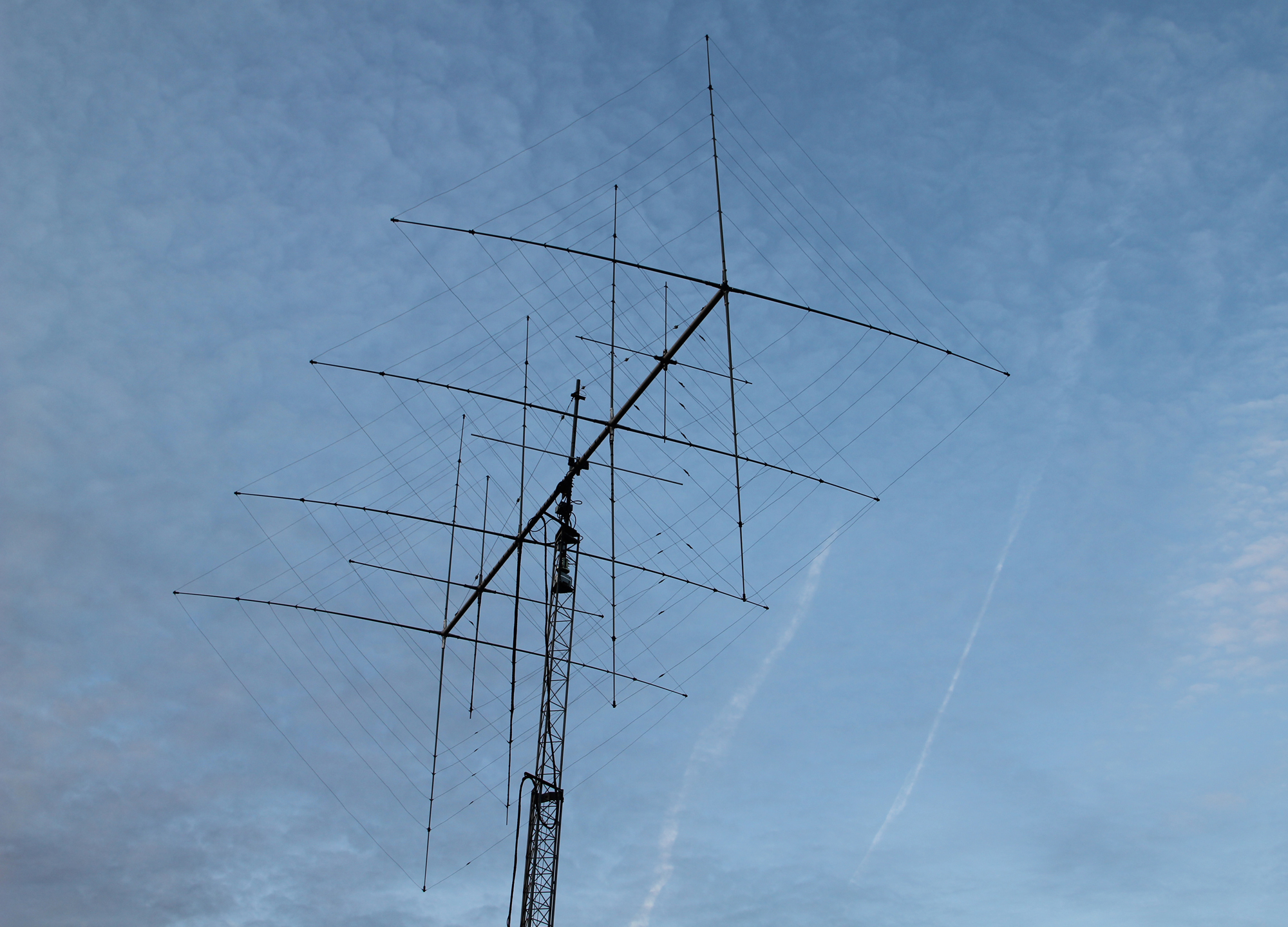
A few years ago, I was fairly intent in moving away from ‘Yagi’ type antenna to loops. Having designed [many] Delta Loops for various bands [I think we sold over 1000 units at Vortex between 2008 and 2020], I was determined that the ‘Full-Wave Loop’ was the way forward.
Saying this, my QTH had different ideas and whilst I have nearly ¾ of an acre to play with here in Eastern England, my house lies within a conservation area and a location of historical interest. Our house is over 300 years old [the ones with a straw/thatch roof] so we can’t just cut down trees at will or perform unlicensed modifications. We’d end up in court with a hefty fine.
This was the main issue here. The ‘Back Yard’ [so to speak] has quite a few straggly and quite high trees. A Yagi I can get by without any issues – but a Delta [or Quad] for instance, would get tangled up in the foliage and quite badly. Whilst we are allowed [within reason] to trim things back and keep everything reasonably tidy – my initial experiments to see if a Delta would fit proved fairly fruitless as a test on a 2 element 20m loop proved an issue as it got badly tangled up in the greenery so it was decided that [and with deep regret] that I couldn’t progress the project much further.
However, during the initial experimental period, I came across a really informative website by KG6B Bob Hume [sk]. The site looked to have been the original work done by KG6B as the operator had been SK since 2011 but still available for reference which was a nice touch and thought by the administrators.
The amount of really useful info still available gave me some great impetus to advance my quest to construct a ‘BIG’ 5 band quad that would work. So, after some extensive reading, KG6B’s info became an invaluable starter to the project. Bob’s site gave potential constructors some vital info on any quest to take on this project. For starters – it’s a big antenna. Four full size loops on 12/15/17 and 20m and 5 on 10m on a 30-foot boom [just over 9.2m]. You’re going to be a big signal, but the array needs a lot of input on the construction side and even more on the electrical side. It requires dedication and a fine attention to detail.
What became apparent from the outset was that Bob had meticulously been through every construction step and pointing out the potential pitfalls along the way. Many hours of modelling were performed and then real-world evaluations runs side by side. It was a herculean effort but as genuine constructors can see from the original documentation that I managed to salvage; Bob was super keen to get everything right.
What I did was to look at the model and each of the plots for all of the bands. Over a period of time, I was able to improve an already outstanding design. In the later part of 2015 I was ready to start buying hardware in order to put the project into motion, however when doing a test in the spring of 2016 it became very apparent that because of the limitations of my QTH, the project would never fly.
It was a real bad day. I’d put many hours and days into honing an already great design but in the end – reality set in. My QTH just wasn’t up to it – so I gracefully bowed out.
What we’ll do here on Q82.uk is to publish the additional work and models that I set out to achieve. Whilst Bob KG6B is obviously SK, in typical ‘ham spirit’, I’ve enclosed the downloads from Bob’s site which I did when first experimenting.
If you have the room and space, then this is a serious 5-band antenna with a nice boom size. It’s not overly long at 30 foot but you will certainly need a plot without too much of the ‘Green-Stuff’ growing in the near vicinity.
I would have really loved to build this, as I know from experience that the ‘Loop’ will blow the ‘Yagi’ into the weeds every time. On paper some of the gain figures may look similar so some operators will question what all the fuss is about. Go on air and it’s a ‘Chalk and Cheese’ affair as we say in the UK.
The Loop/Quad will be first in on the pile-up and last out. Ask any ‘loop’ owner. If I ever move QTH, this will be my first [and only] mid HF to 10m beam for sure.
Thanks to KG6B.com. We’ve used their content but we are sorry to see that the URL now seems to have been closed since 2019.
Q82.uk is happy to publish works from silent key operators who I’m sure would be happy to extend their knowledge to new operators and new people into hobby.
Thanks to Bob Hume KG6B for his work and dedication to a great 5-Band monster Quad. He did all the real work, I just tried to make those few minor improvements and updates which I think we managed to do.
So, you want to build this baby. Well, there’s 2 options on the table. You can follow Bob Hume’s original designs or read down further to see what improvements we’ve manged to eek out of the design.
BUILD OPTION 1 – Bob Hume [KG6B]
Original Design, Data, PDF’s and EZNEC File:
Bob Hume’s original work was to create a model using MATLAB. Matlab is a a programming platform designed specifically for engineers and scientists to analyze and design systems. The idea was to export the Matlab file into EZNEC. As I didn’t have access to Matlab, I used Bob Hume’s original wires data and put them manually into EZNEC. It took quite a while but was well worth the effort.
The original EZNEC model assumes that each loop is constructed using 12AWG or 2mm bare copper wire. Don’t use PVC coated wire as the velocity factor will be totally different and your antenna won’t match the model even closely.
The antenna operates as 4 elements on 20, 17, 15 and 12m. On 10m, the array has an additional ‘5th element’ as the spacings based on 4 elements are not optimal.
My first initial though were not the size of the array, but effectively feeding the quad and how that feed arrangement would successfully work. Normally, a single feed [especially for multiband quads and loops] doesn’t work that well – but there are measures that the builder can take to alleviate symptoms such as RF currents following back down the coaxial feeder in an attempt to isolate each individual loop and minimise coupling between loops.
Here is the feeder info for each band. Note, each band is fed separately. IE – one feedline per band. We’d suggest putting ferrite beads over each feedline [like a W2DU Balun] at the feed point to remove any potential unwanted common-mode currents on the feedline. Rather than buy one, users can make their own using ‘Type 43/31 or 52 beads’ – all will do a similar job.
Quote from the original documentation by KG6B:
“The coax feed design for the five band quad is shown below which gives the coax feed line lengths to a mast mounted remote coax switch box. The switch box should be able to short the unused feed lines to ground. This feed line design is important to prevent interactions between driven and non driven quad sections that can degrade the gain, front to back ratio, and SWR of the antenna. Any length of RG213U can be used from the switch box to the shack“.
Here’s the run-down of the feeder lengths for each band. We think that most constructors will use an antenna switch that switches 5 [or more] coax lines. Here’s the lengths of coax that are required between the feed point of the loop and the ‘switch box’. The switch box ‘SHORTS’ un-used feedlines to ground. We currently have our VRAT MKII [Vortex Remote 6-Port Antenna Switches] which are NOS [New Old Stock] Vortex units. These have the option to manually place jumpers on the PCB [thus shorting out un-used lines to ground] which you need to do. Once set, it’s put the cover on and forget. Need a Vortex VRAT MKII Switch Box? [I’ve only a handful remaining!]- see here how to order one [limited stock].
20m – 50 ohm section RG213 [20.46 feet]
17m – 50 ohm section RG213 [17.71 feet]
15m – 50 ohm section RG213 [16.31 feet]
12m – 75 ohm section of RG11U [78.2 inches]
10m – 50 ohm section RG213 [22.22 feet] – YES CORRECT!
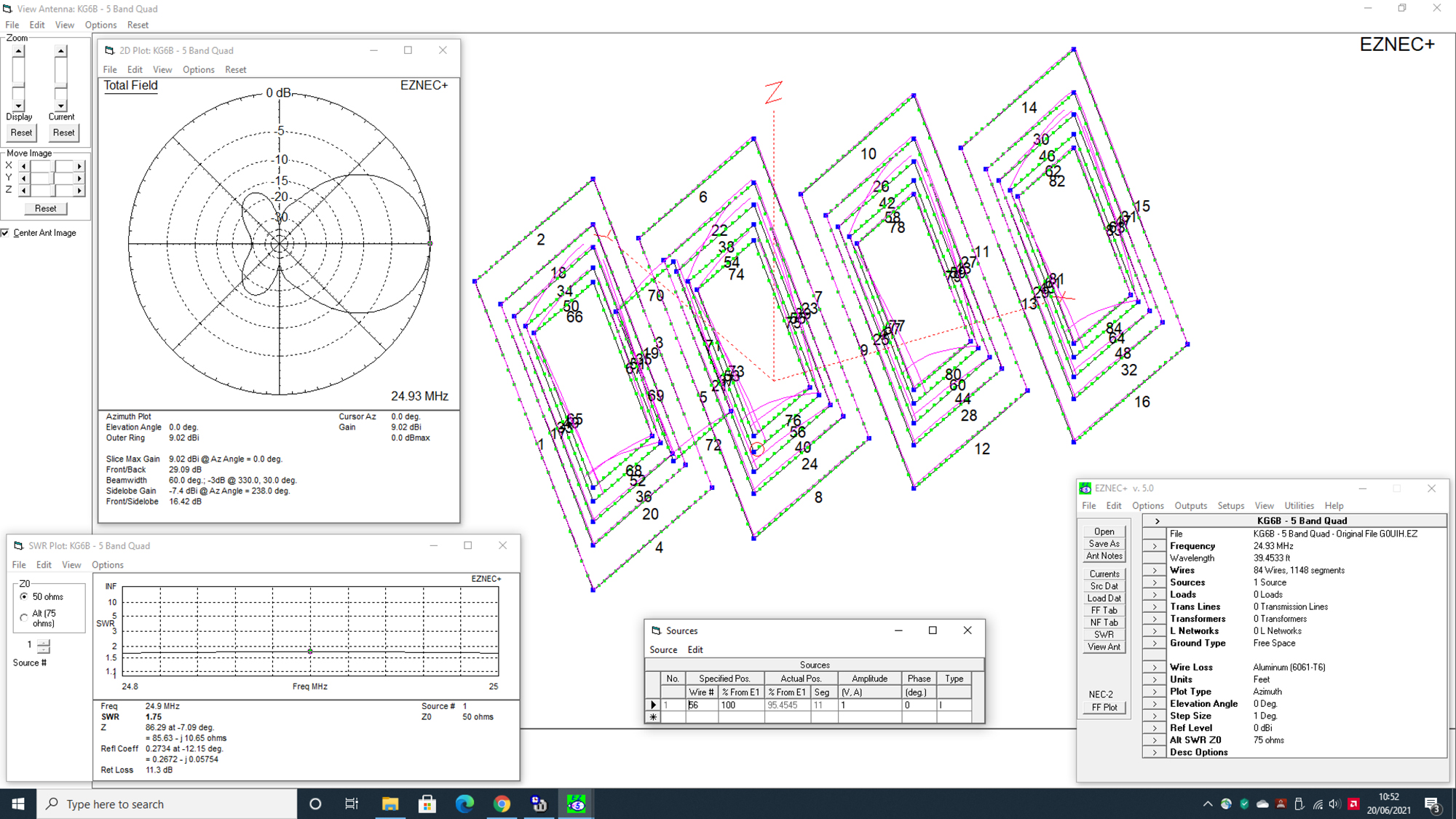
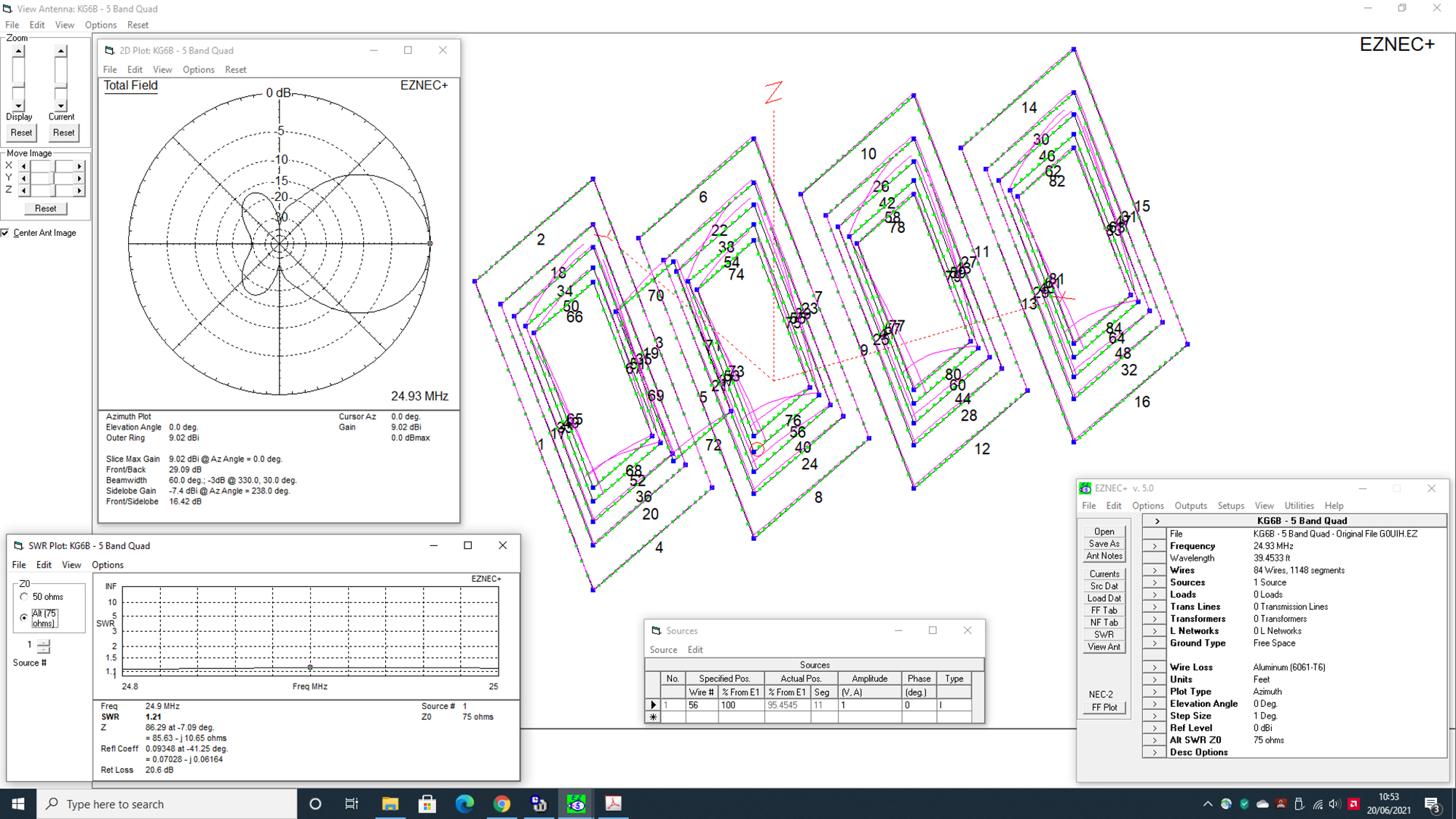
Readers will note that the 12m loop needs to be fed with a quarter-wave 75 ohm transformer. RG11U [or any good quality 75 ohm coax] will do the job. See below the 12m plots when fed directly with a 50 ohm feed and in comparison when fed with a 75 ohm ‘Q’ section. You can see the 75 ohm section improves the SWR nicely.
So – before you decide on the original design, lets take a look at the table below as I’ve made some modifications to the design. I don’t use any EZNEC automated optimisation methods [like ‘Auto EZ’] for example. Everything is done manually. It takes a while, but you then really understand the software and can see what changes affect your build which means you can then understand your own design much better.
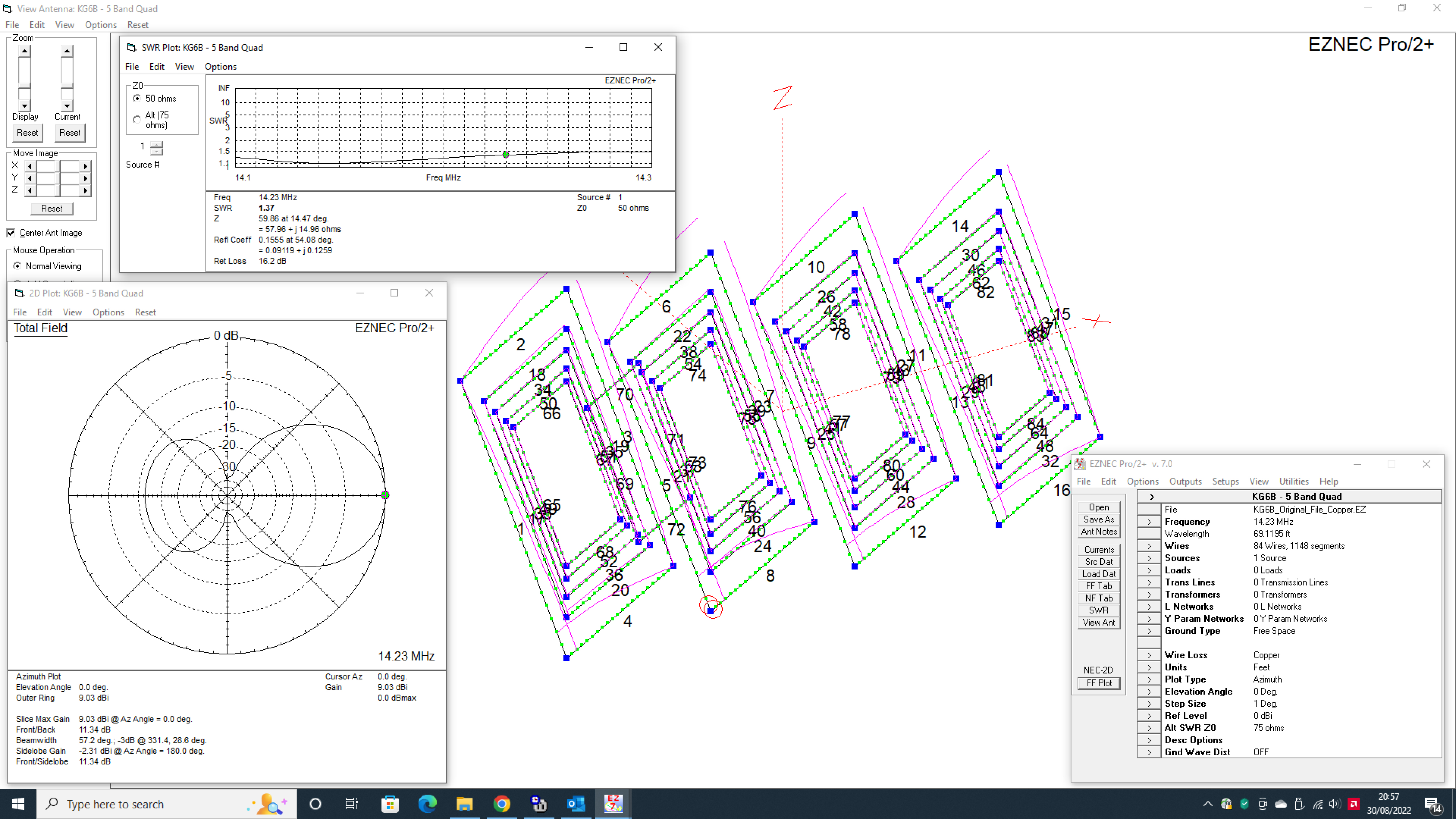
| ORIGINAL KG6B DESIGN – 12AWG Bare Copper Wire | Forward Gain | Front to Back |
| 20m – [14.230MHz] NB: Front-to Back ratio is very poor | 9.03dbi | 11.34db |
| 17m – [18.140MHz] | 9.22dbi | 17.01db |
| 15m – [21.250MHz] | 9.30dbi | 23.04db |
| 12m – [24.930MHz] | 9.13dbi | 30.55db |
| 10m – [28.450MHz] | 10.53dbi | 25.14db |
Download Bob Hume’s Data here:
5-Band Multi-Element Quad Modelling with EZNEC4 and MATLAB
5-Band Multi-Element Quad Design and Coax Feed System
5-Band Multi-Element Quad – Construction
5-Band Multi-Element Quad – Original EZNEC File by G0UIH [Based on original KG6B Data]
For users that don’t have EZNEC – we’ve created a KG6B original data sheet
**NEW January 2022** – EZNEC Pro/2+ is available as a FREE download from W7EL
BUILD OPTION 2 – Steve [G0UIH]
Data, PDF’s and EZNEC File:
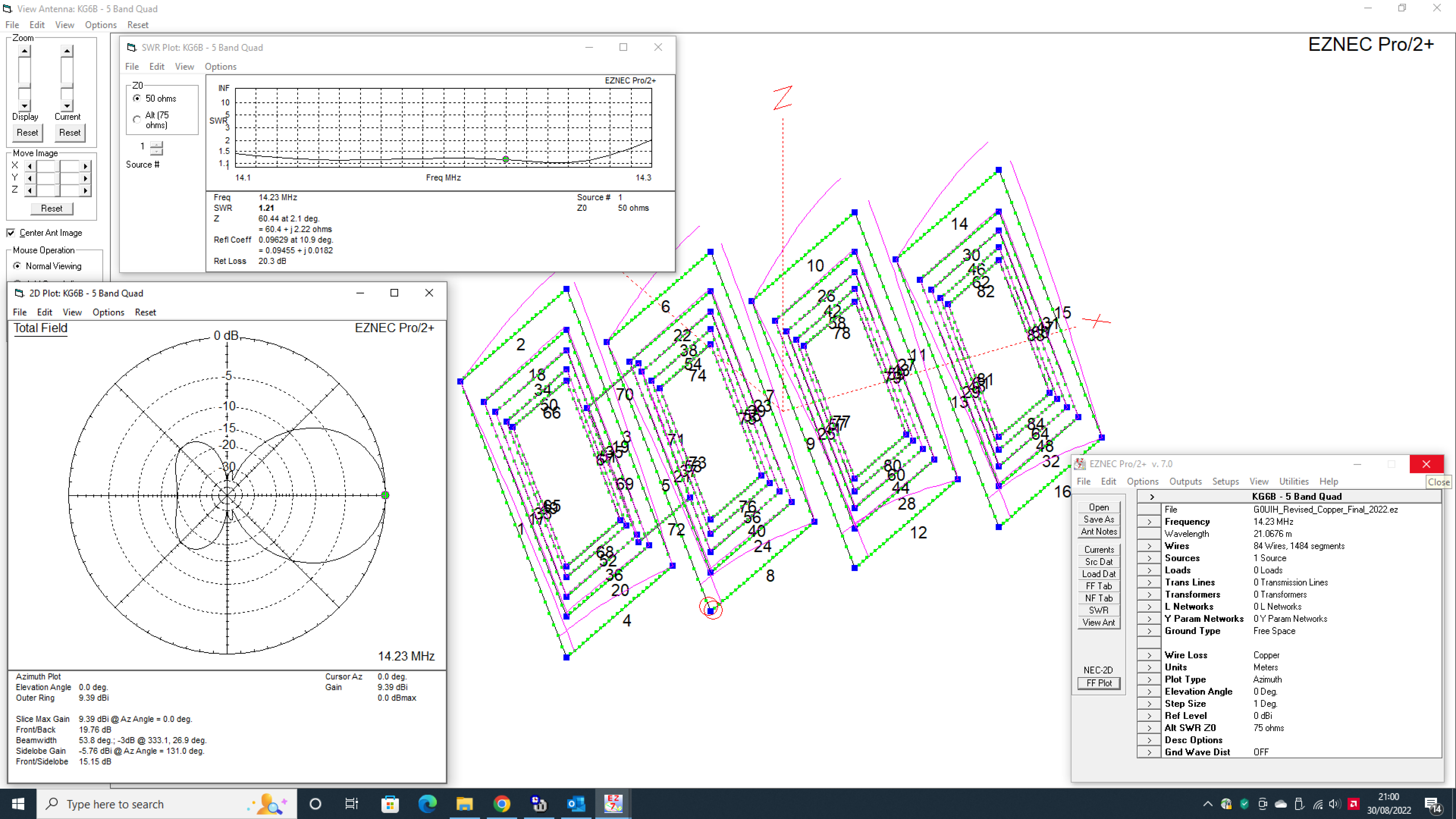
It took me a while to manually import all of Bob’s data into an EZNEC file but I used the opportunity to see if I could improve on the original results. Improvements are shown in ‘Green‘ and have a ‘+’ symbol. Reductions are shown in ‘Red‘ and have a ‘-‘ symbol. As you can see, there’s nice improvements across the whole range. We’ve sacrificed a minor reduction in 15m front to back in favour of a gain boost.
| G0UIH – MODIFIED USING 14 AWG [1.6mm] Bare Copper Wire | Forward Gain | Front to Back |
| 20m – [14.230MHz] Note – Far better SWR curve | 9.39dbi (+0.36dbi) | 19.77db (+8.89db) |
| 17m – [18.140Mhz] | 9.58dbi (+0.36dbi) | 20.85db (+3.84db) |
| 15m – [21.250MHz] | 9.43dbi (+0.13dbi) | 20.41db (-2.63db) |
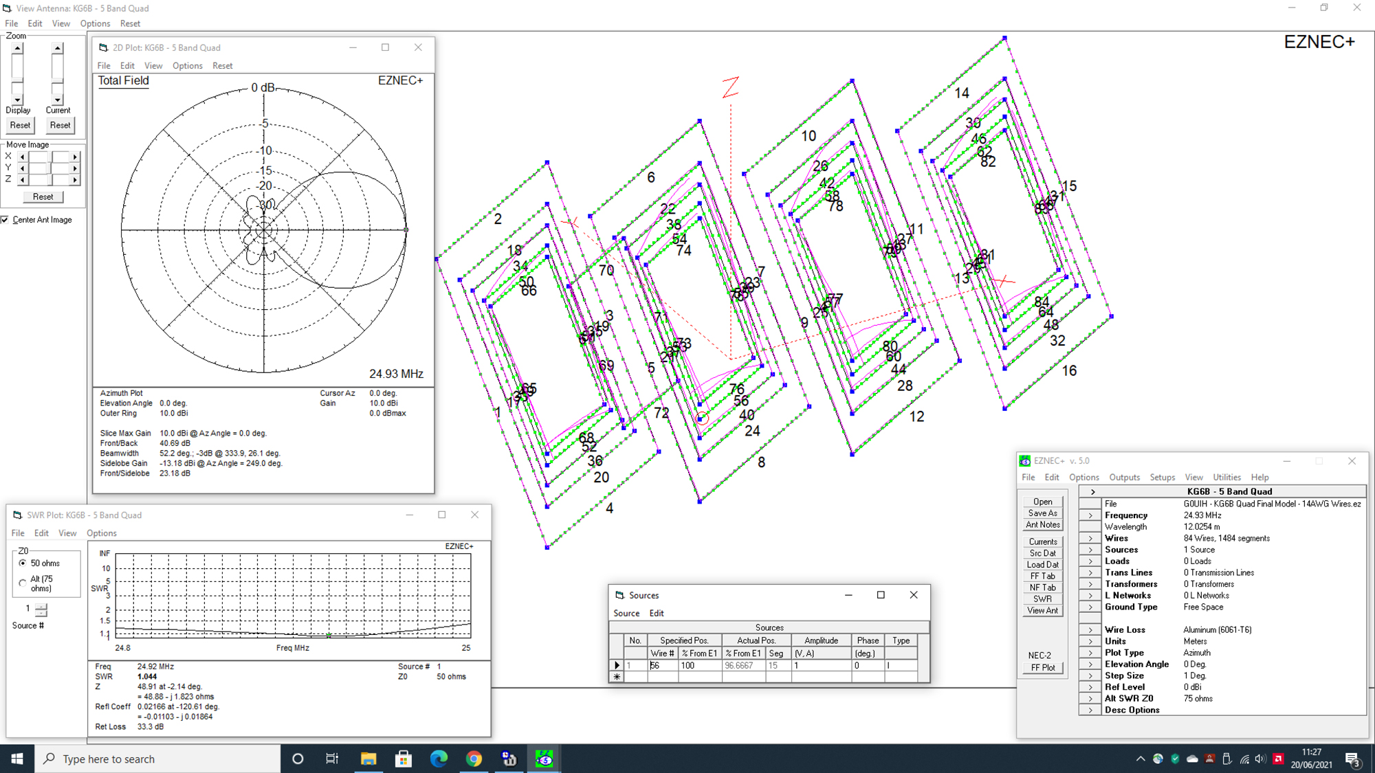
| 12m – [24.930MHz] | 10.27dbi (+1.14dbi) | 33.64db (+3.09db) |
| 10m – [28.450MHz] | 10.70dbi (+0.13dbi) | 28.40db (+3.26db) |
An additional bonus with some careful modelling, the 12m loop can now be fed directly with a 50 ohm quarter wave section and not 75 ohm. See the revised plot below.
Constructors should be aware that the G0UIH model assumes the builder is using 14AWG [16SWG] bare copper wire [1.6mm] rather than the much heavier 12AWG [2.05mm] wire in the KG6B original. Users can see from the link that 14AWG [American Wire Gauge] = 16SWG [Standard Wire Gauge]. SWG is the gauge used mainly outside of North America. You can see the conversion table here.
The stock shown by Martin Lynch & Sons is 1.6mm so is ideal and it’s hard drawn antenna wire that has been pre-stretched. We think that 16SWG is fine for most users and additionally that the thicker wire may encourage additional ice build up during winter. 16SWG of course is also cheaper and lighter but still strong enough yet will still withstand QRO without issues.
For this build, we estimate that you’ll require about 325m of wire for all loops so 7 packets will do the job with plenty to spare. Unfortunately, the outlets that do seem to stock the wire only seem to sell in multiples of 50m although you may be able to get longer lengths from the [various] manufacturers.
UPDATE SEPT 2022:
Tnx to Des GI0UTE for highlighting that we had modelled the revised data in aluminium rather than copper. We’ve also included a ‘Split Current’ feed point [SI] as recommended by Bob Hume. Selecting ‘Copper’ as the preferred material actually improved figures slightly.
Revised modelling showed that the SWR curve on 20m was much to ‘Peaky’. It’s now below 1.4 to 1 over the main 14.100 to 14.300 section of the band. I’ve done a revision and the new file is available to download below. The tables above have been updated accordingly.
Download G0UIH’s Data here:
5-Band Multi-Element Quad – New 2022 EZNEC File by G0UIH
For users that don’t have EZNEC – a new ‘2022 data file‘ is available here

