Building a 1:1 Choke Balun
On an antenna system, a choke balun is used to create a high-impedance to common mode currents that would flow on the outside of your coaxial cable [the shield]. These common mode currents can cause all kinds of problems such as RF in the shack and matching problems – including oddball SWR readings. So, minimizing common mode currents is recommended.
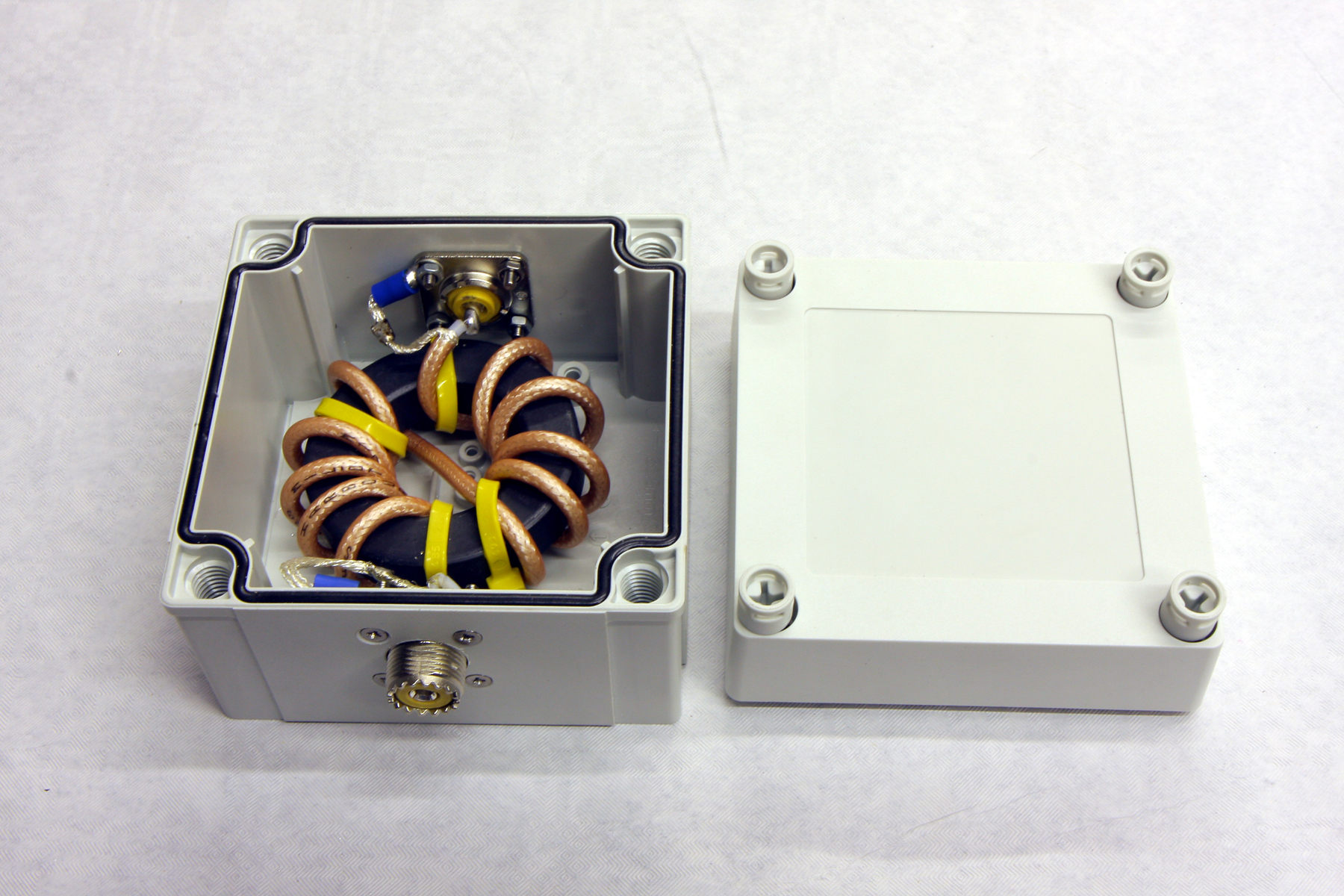
You can use the balun at the feed point of the antenna, or where the balanced part of the system meets the unbalanced part. We call it a ‘Choke Balun‘ because it chokes off the RF on the braid at the point where the balun sits which is normally at the antenna feed point. Also to note, that a 1:1 choke is NOT a balun transformer.
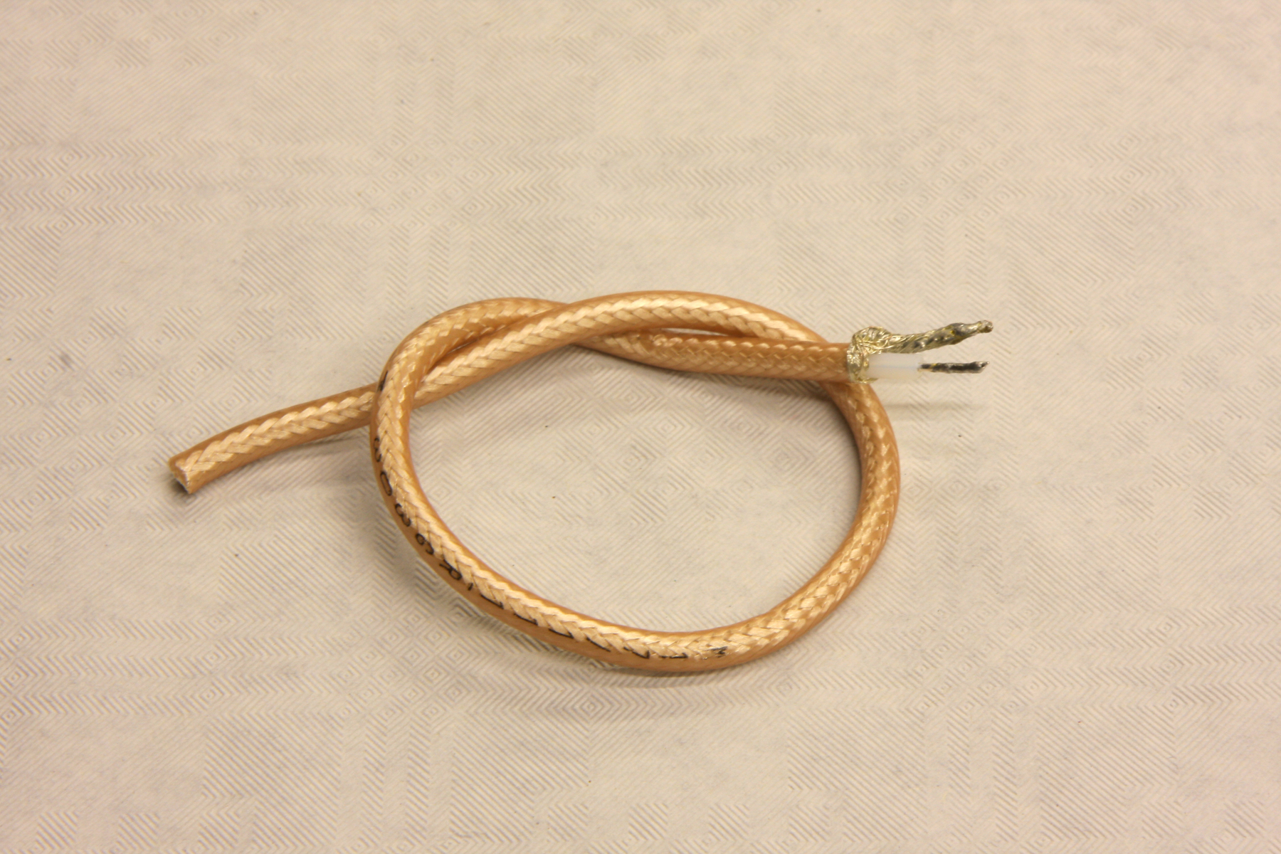
We’d suggest that either RG303 or RG142 is used. Both a very similar electrically and will handle 3.5kw at 30MHz
If you are only using up to about 500w – then RG MINI8 would be a good choice of coax
As we are using a choke balun with a 1:1 ratio, this means that no impedance transformation takes place. In essence its 50 ohms in and 50 ohms out. Unlike a 4:1 balun where an impedance transformation happens, converting the high 200 ohms impedance, on the antenna side down to 50 ohms which your transceiver will be happy with.
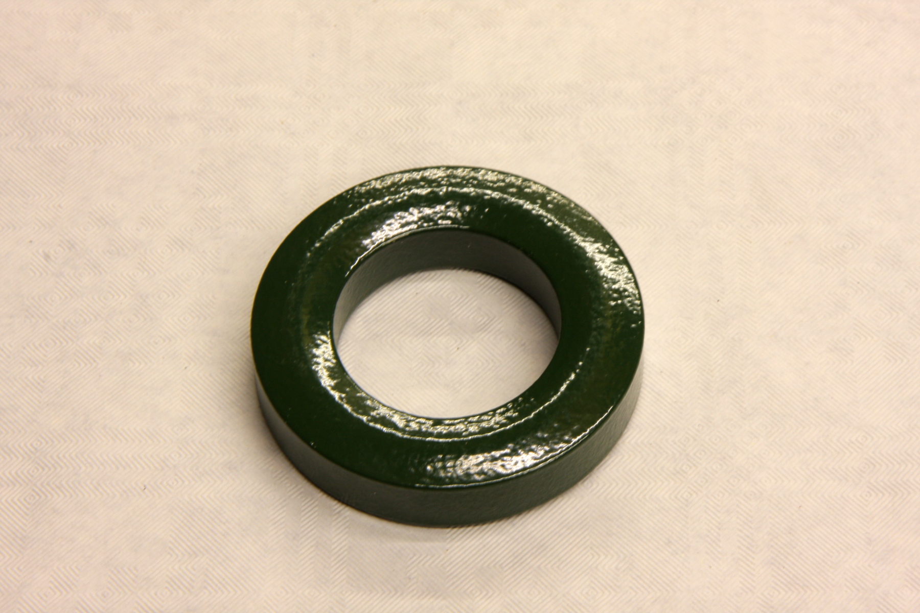
So – how do we build our balun? First we need to choose the correct ferrite core. Using any old core from the parts box is not on the cards for this excersise. Let’s mainly concentrate on HF for starters. Lower HF band users, particularly 160, 80 and 40m aficiandaos should look towards using a 240-31 type core. The numbers in the core identification are quite easly to follow.
‘240‘ means the core is 2.4 inches in diameter and ‘31‘ is the type of ferrite used in the core. Type 31 ferrite is extremely good at attenuating common mode RF currents in the lower band frequencies.
The amount of attenuation is expressed in Ohms. What we need is the most ohms to do a good job. This attenuation is known as ‘Choking Impedance‘ [CI]. The type 31 ferrite is the best core for the lower HF bands and a choke wound with 11 turns of of RG303 coax on a type 31 core such as a 240-31 will give a high choking impedance on the lower bands. There’s plenty of discussion on the web about how much CI is required for an efficient choke. A site in the US states that 500 ohms is the minimum although most professional manufacturers say from 1000 ohms upwards.
The amount of CI will differ as the frequency changes but users can expect levels of up to 4000-5000 ohms using this core on some parts of the low bands.
Another great and very useful general core is the ‘240-43‘ type ferrite. The ’43’ has a wider frequency span than the ’31’ although it’s less effective on the lower HF bands. We’d say that a 43 is good from 40m [7.00MHz] upwards and is still reasonable at 10m. Above 10m, the CI drops quite rapidly and would not be suitable for say 6m use.
What should be noted is that the higher in frequency you go, the less turns on the core you need so you have to try and retain a happy medium when designing baluns for broadband use.
Another great core that we can recommend for the general HF bands [again from 40m upwards] is the ‘K‘ or type ‘52‘ core. This core is a relatively new boy on the block and hasn’t been around for too long. There is little difference between the ‘K’ and the ’52’. They are [for this exercise], pretty much identical in their electrical properties. A ’52’ is good for 40m and higher and will also work up to the 6m band, albeit with reduced CI.
For the higher HF bands [12/10m], a type ’61’ core comes into its own. I’ve been running 2 stacked type 61 cores [240-61] with 8 turns of RG303 PTFE coax on a 6 element 10m OWA Yagi for about 7 years. VNA analysis show over 6000ohms choking impedance at 28.450MHz and it easily handles full legal limit. It also makes a good core for use on 6m and even 4m.
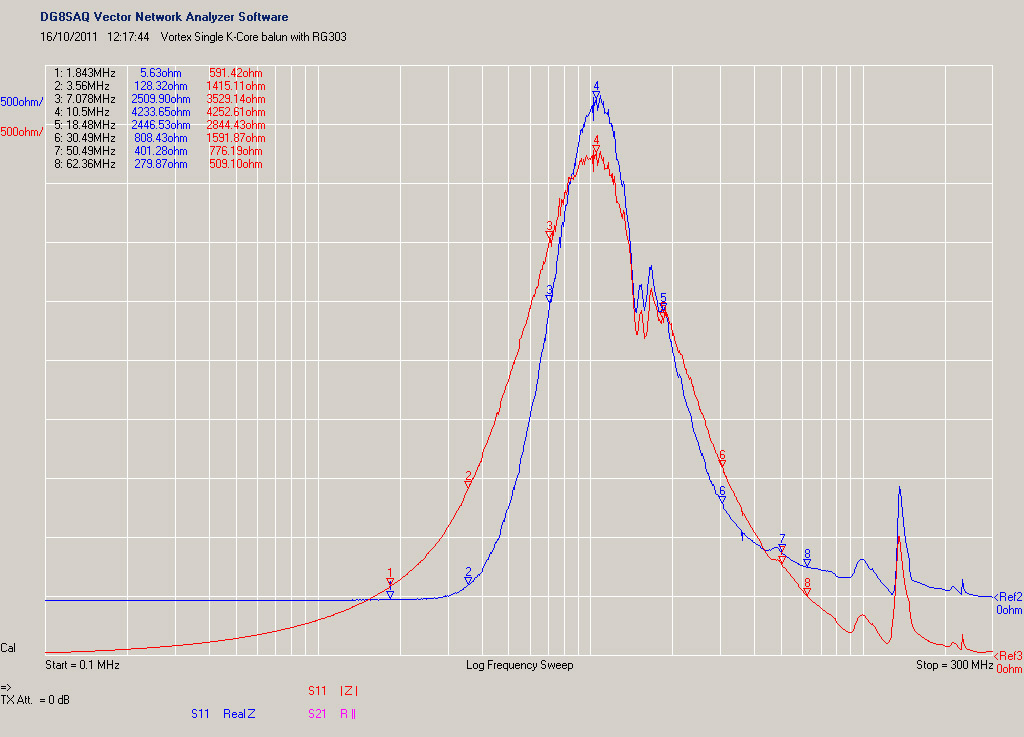
Readers who own a VNA [Vector Network Analyser] will know exactly how to test a choke balun. The above image shows the analysis of a 2.4 inch ‘K’ ferrite. The balun had 11 turns of RG303 PTFE coax wrapped around the core. You can see that generally across the mid/high HF bands it’s quite respectable. The choking impedance at 80 and 160 meters is reduced and a type 31 core would perform much better at these frequencies. Here we can see from 40m upwards, good levels of performance. It still not bad at 10m either and is even usable [to a point] on 6m.
MOAB [ Mother of all Baluns]
As they used to say on ‘Blue Peter‘ – “here’s one we made earlier”.
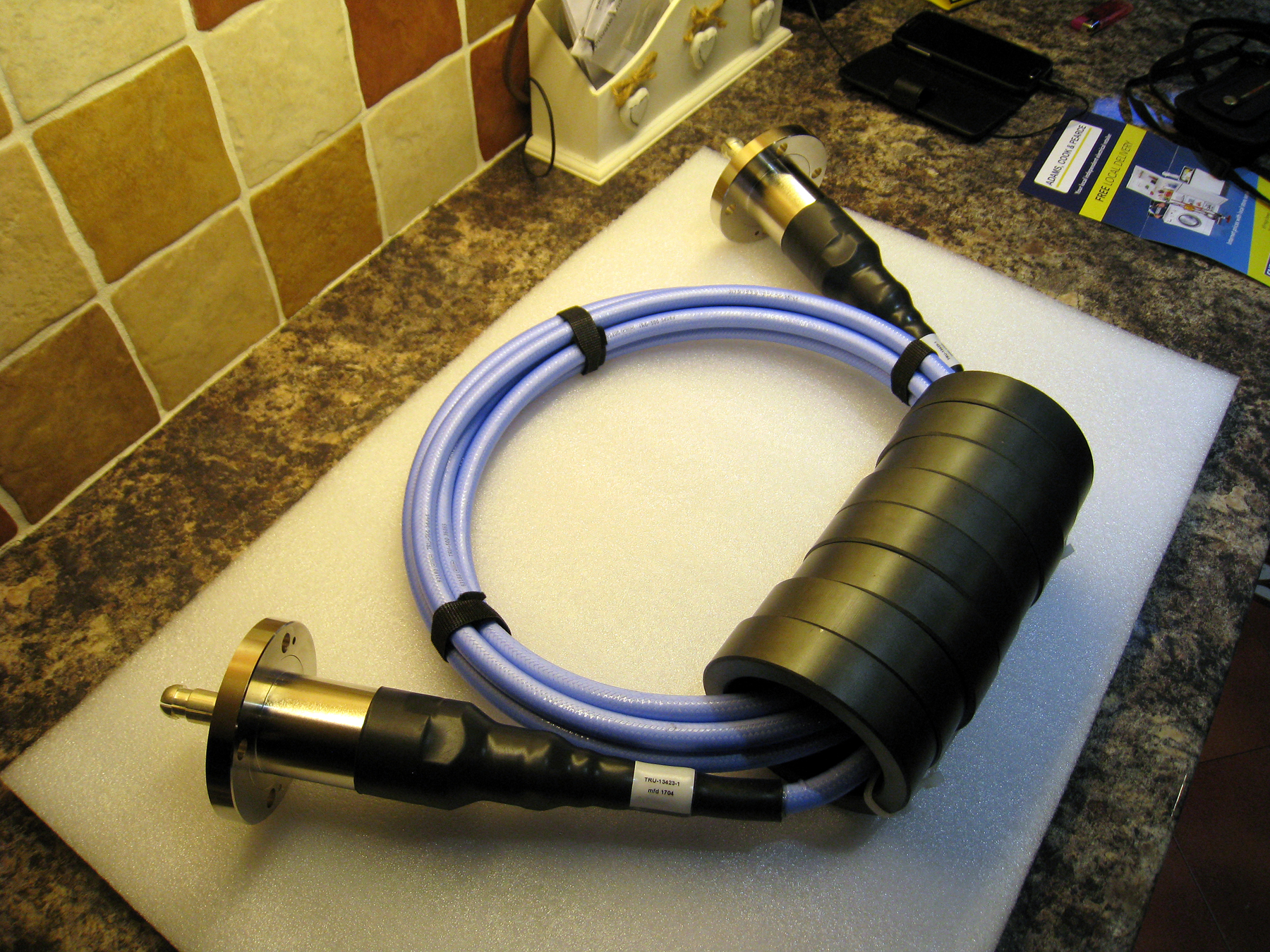
This is really the MOAB. Designed for use at lower HF for military service. We used 8 x 4 inch 400-31 ferrite cores manufactured by Fair-Rite in the USA. The design criteria was to handle upwards of 20Kw RF power levels in the lower regions of HF [Between 4 and 7MHz].
The VNA check showed a balun choking impedance of over 10,000 ohms using 5 passes of TRU-500 coaxial cable. The cable itself is rated at 12kv and can handle well over 50kw at the design frequency. The cable actually handled more than the hefty EIA 1 5/8ths inch connectors [and they were pretty robust 🙂 ]
Need a balun for your station? – If you don’t fancy building your own, then why not check out Balun Designs in the USA. I have two of their products and they are very well constructed and each product seems to be backed up by valid technical data. There’s a balun for nearly every occasion including various impedance transformers and specialist baluns for ATU’s.
Where to purchase balun & transformer cores
See our page here on where the best place is to get your ferrites from.

