
Icom 706MK2G – FM Transmit Frequency is 10kHz off. VCO Trimmer Drifts Over Time
My Icom 706MK2G is now 26 years old and over the years, I’ve performed a few mods like the fan speed adjustment, improved SSB audio TX [now at 3kHz], an amp keying circuit and a few other mods that make a good radio, really great.
The unit has always performed really well and been dragged around the world on many occasions, working from many hot and sweaty Pacific island locations. Over this time, it’s never missed a beat and never let me down.
However, this week [whilst using it to test a friend’s amplifier] I noticed a real oddity. On FM transmit, the actual transmit frequency was about 10khz adrift of the shown frequency on the front display.
This didn’t seem right and I also noticed the power meter dipped sharply when transmitting on FM. For example you transmit 5 watts, but on voice, the power meter dipped to about 2 watts. That’s more like what I’d expect on AM – somethings not right.
An online search found a valuable resource from KV5R who explained that over time, the FM VCO voltage adjust variable can get dirty and lazy.
The normal VCO voltage at this point should be around 1.8v measured at full power key-down on FM at 29.100MHz.
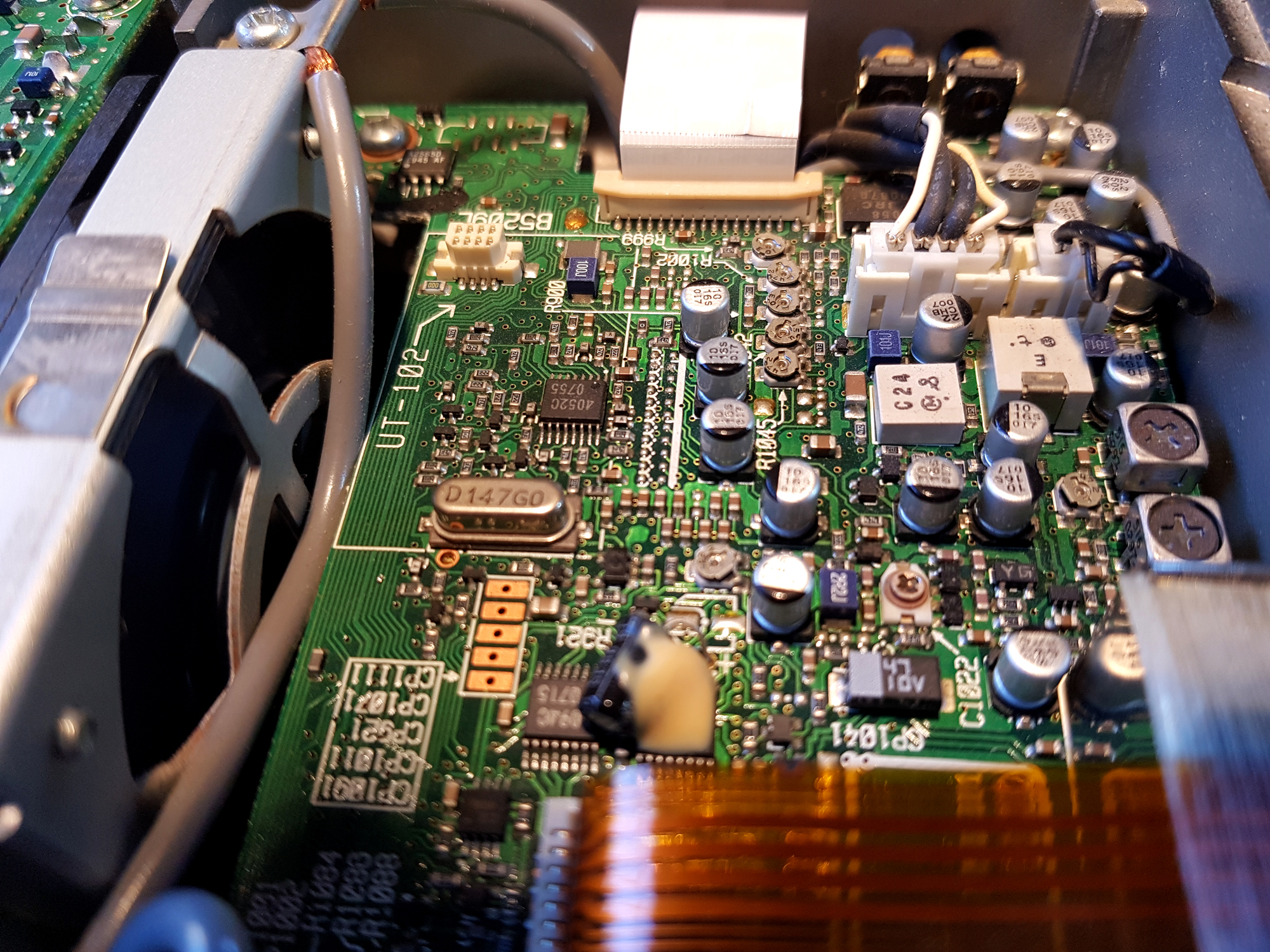
On the image below, the top arrow indicates the test point to use [CP1011] which is on the ‘Main Unit’. Just unscrew the top cover to reveal.
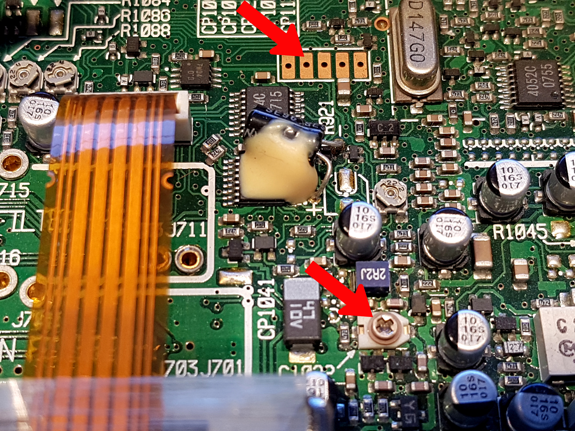
The adjustment is made by rotating the small variable capacitor which is C1022 as shown in the image as the bottom arrow. When initially checking, my own unit had drifted to around 0.3 volts so the VCC was gasping for some power.
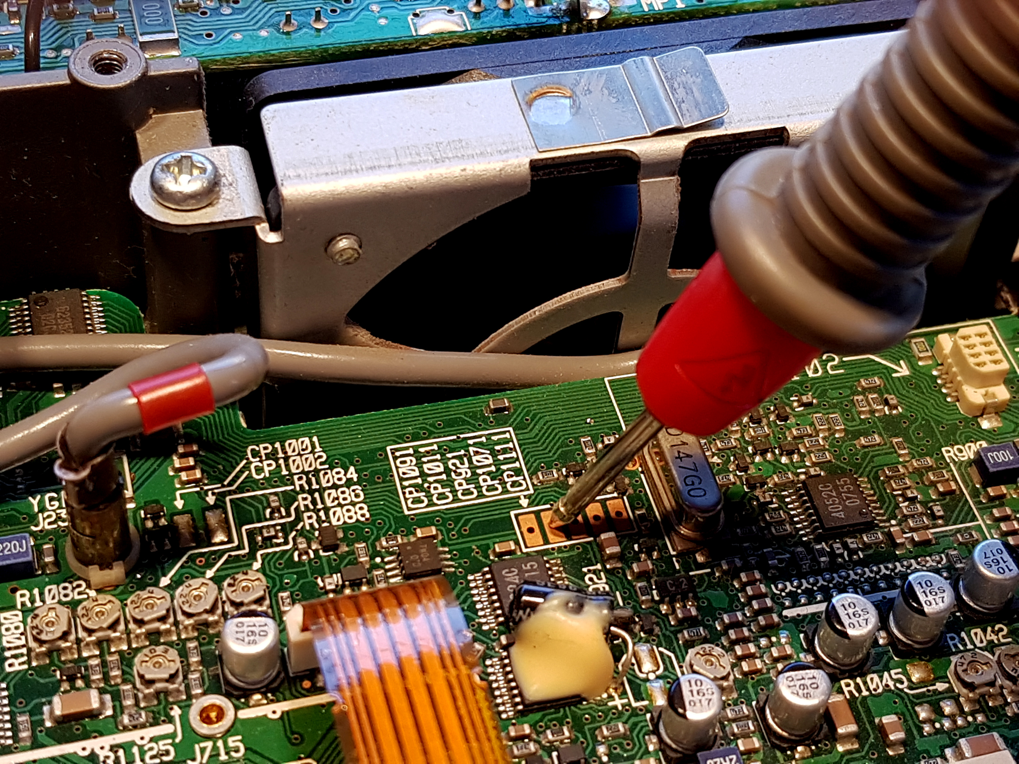
You need to use a small jewellers screwdriver to make the adjustment. I actually used a small swab of switch cleaner and slowly rotated it back and forth a few times just in case it was a little dirty.
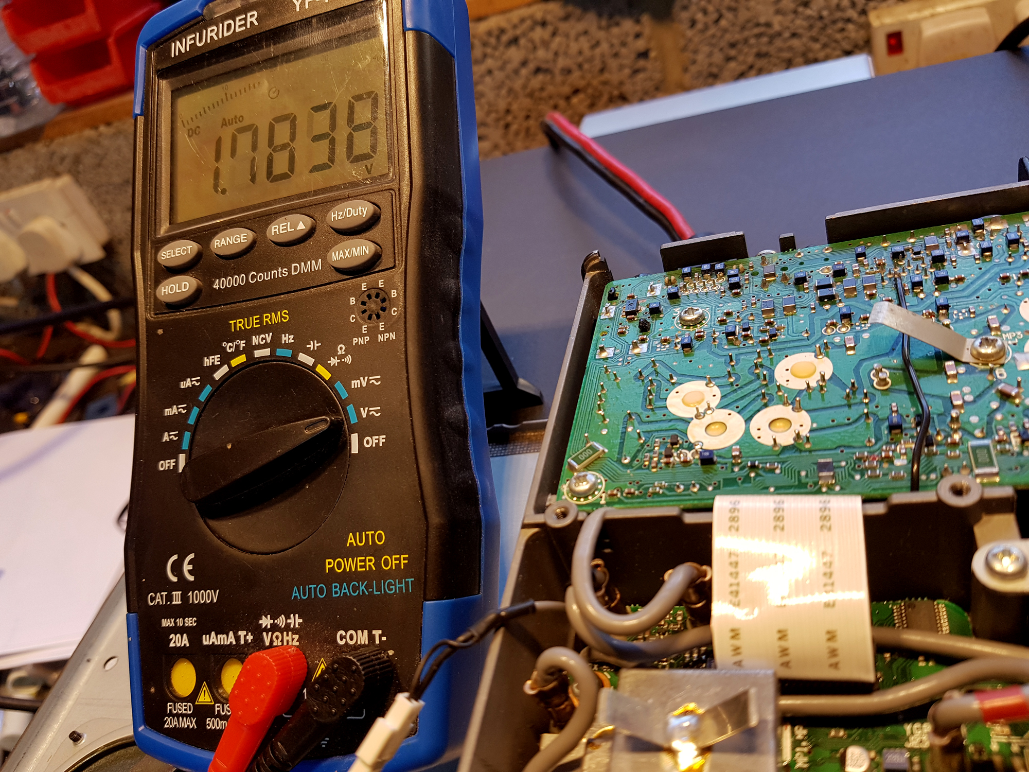
As you can see, it’s now set around 1.8v and now working perfectly. Power output is now 100% stable and transmits on the correct frequency.
Download a PDF from the IC706MK workshop manual to show the test point and trimmer location. Job done and thanks to KV5R and his online resource.

