
A Home-Made ‘Gain-Master’ on Steroids
I’m sure whilst searching the net, many prospective homebrewers have come across various designs based on the original ‘Sirio Gain-Master’. It was quite a revolution when it took off.
At Vortex, I had created a similar ‘Concept’ in our first Q64 in 2008 [two years before Sirio launched the GM] when I began selling commercially – the ‘Q’ being the key is the headline. In essence, the Q64 was a .64 wave length vertical antenna which used a coaxial ‘Q’ section in order to match the antenna. The ‘Gain-Master’ employs similar techniques so there isn’t any real magic going on here.
However, I hold my hand up here. I made one error in that in the original Vortex Q64 design, the ‘Q’ section was left out in the open to the elements. In [most] cases, this didn’t present an issue – but some users found that in wet weather, the rain/water on the outside of the coaxial ‘Q’ section effectively changed the velocity factor of the coax. OK – not by much, but enough to shift it 500KHz down the band – hence we had some questions from some buyers.
Obviously the Sirio guys had the upper hand here and their final commercial version was sleeved into the fibreglass section. Any bad weather therefore had no effect on the resonance. So, we all learn.
The subsequent Vortex Q64 MK2 steered way from the ‘Q-Section’ transformer, adding a solid external hairpin which apart from doing an excellent job in matching, virtually removed any power limitations. You could literally pump kilowatts into it. The only limiting factor was the feed socket and 14 gauge ‘Flexweave’ link wire.
The ‘Gain-Master’ [in the early days] originally had a 1kw power limitation which had to be reduced because of coaxial capacitor failures. The subsequent reduction to a miserly 500w key down limitation wasn’t enough for many users. I’d heard of a few horror stories mainly of ‘Fried’ upper capacitor sections which were constructed from a coaxial section.
It was a bit hit n’ miss, because depending on how well the coaxial capacitor was ‘trimmed’ from the factory, this would dictate how much power the antenna would handle. Saying that, not many would handle 4 figures without arcing problems.
The original Vortex Q64 used ‘Westflex 103’ from Henry Westlake [The original creator of W103] in the ‘Q-Section’ and would certainly handle well over a 1.5Kw so we hadn’t got it all wrong. But, with all of the above – the ‘Gain-Master’ has certainly created an interest over the years. Some homebrewers seem to have nicely created their own versions and with some good results – so hats off!
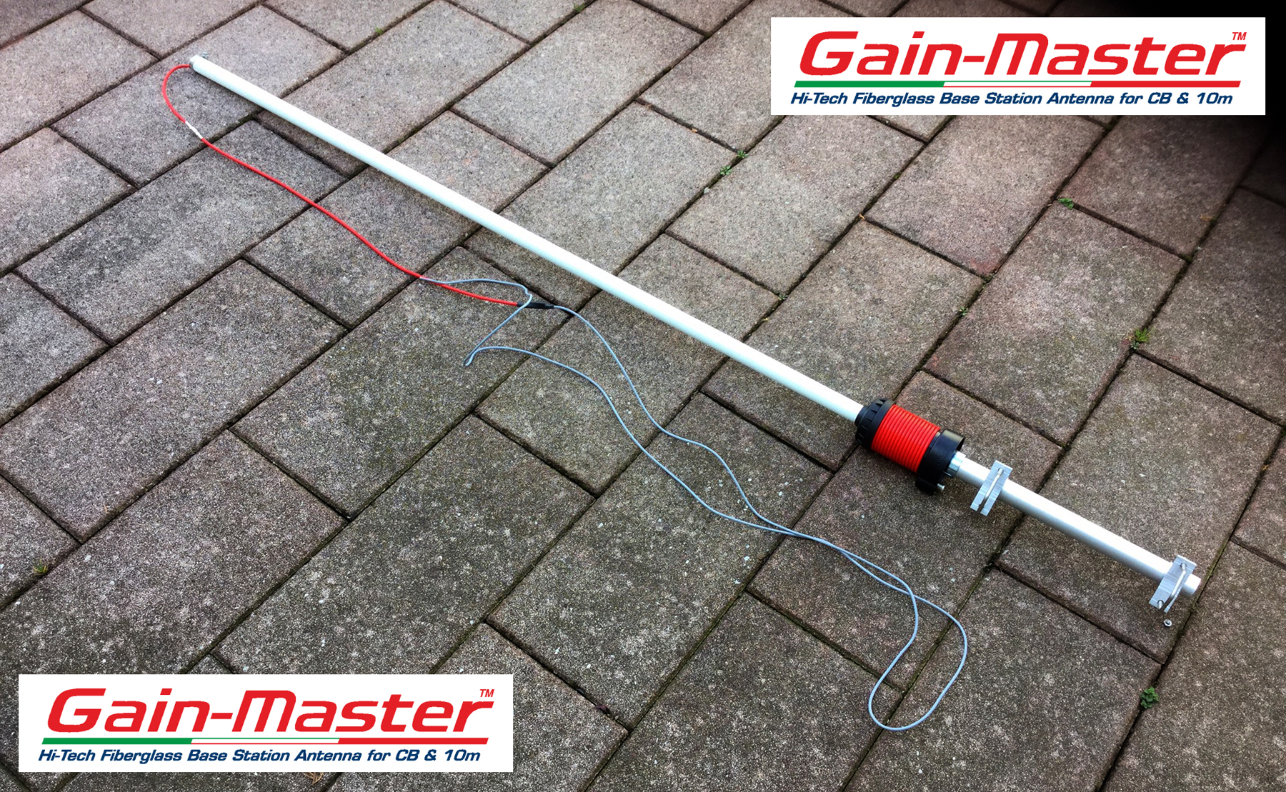
Here’s my initial take on the Gain-Master
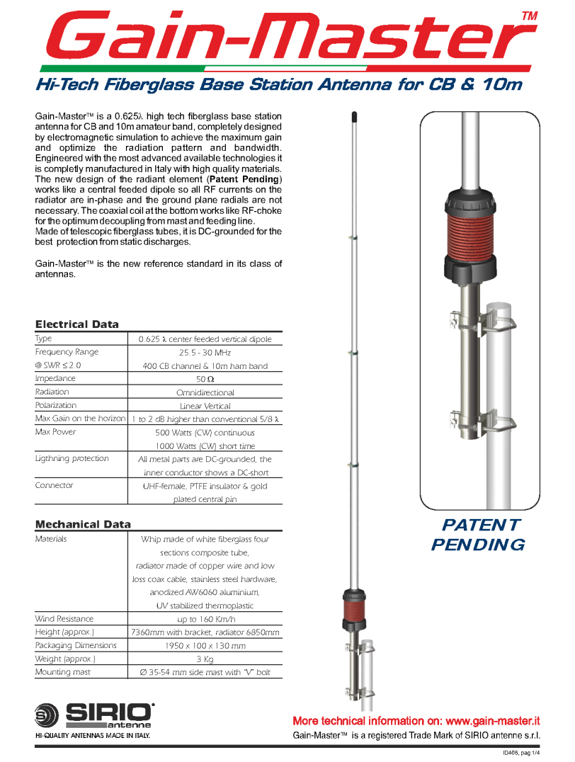
To make things interesting, there’s 2 versions. The original seems to be a 5/8th wave [6.85m in height] and and updated 1/2 wave version [5.56m in height]. Construction seems similar between the two. Sirio market the antenna as a centre-fed coaxial dipole. Saying that, I’m trying to get my head around the ‘Centre-fed’ statement as clearly [physically] – the feed point is at the base of the antenna. Looking at the way its put together does give you a few clues as to why they call it what they do – so it adds credibility. Personally, I’m thinking of a sleeve-fed design like a T2LT/Flowerpot Antenna [or a derivative of either] – but the jury’s out on this one for sure.
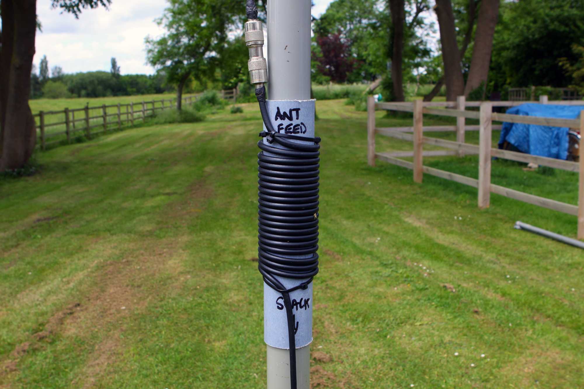
There is an air-wound RF ‘Choke’ at the base. The choke looks to be a half-wave length of 0.66 approx. velocity factor [v/f] coax which is most likely RG58 or similar. The coax is wrapped 16 times around a factory supplied former that’s about 65mm in diameter. The actual length of the choke seems to be around 160 inches [406cms].
Also, the choke is also NOT a balun as some refer, but merely a device for preventing common-mode currents flowing on the coax feeder BELOW where the choke is positioned. The whole array is then DC grounded at the SO239 feed point which sits just below the choke.
There’s an impedance matching stub which matches the [natural] ‘High-Z’ of the antenna down to 50 ohms. The capacitor, which some have said is around 8.5-9pf mark further ‘up the chain’ – removes any reactance.
Constructing and Testing the RF Choke
As only a limited amount of antenna builders reading this will have access to the right equipment to test the choke, we’ve taken all the ‘donkey work’ out of this part of the project. Here at Q82.uk, we have access to a Mini Radio Solutions miniVNA Pro Bluetooth VNA and an extender up to 1.5GHz. For anyone who hasn’t drifted down the route of antenna and RF design, a VNA [Vector Network Analyser] is a great tool to have in your test gear inventory. It [can] take a while to master the functionality but it’s worth taking some time out getting to know it.
One reason for getting the VNA was to measure the choking impedance of both air-core and ferrite chokes. At Vortex, we sold 1:1 RF Choke Baluns [ferrite] but needed a reliable device to measure the amount of choking impedance. Only a VNA can test and give you the electrical characteristics of the device under test.
So we checked out and built our own RF choke for our homebrew ‘Gain-Master’ clone. Rather than use a 2.5 inch [63.5mm] former, we had some nice 2mm fibreglass tube in the workshop. It was sturdy stuff with 2.5mm wall so could be used to form the base of the antenna and be used as a former for the choke.
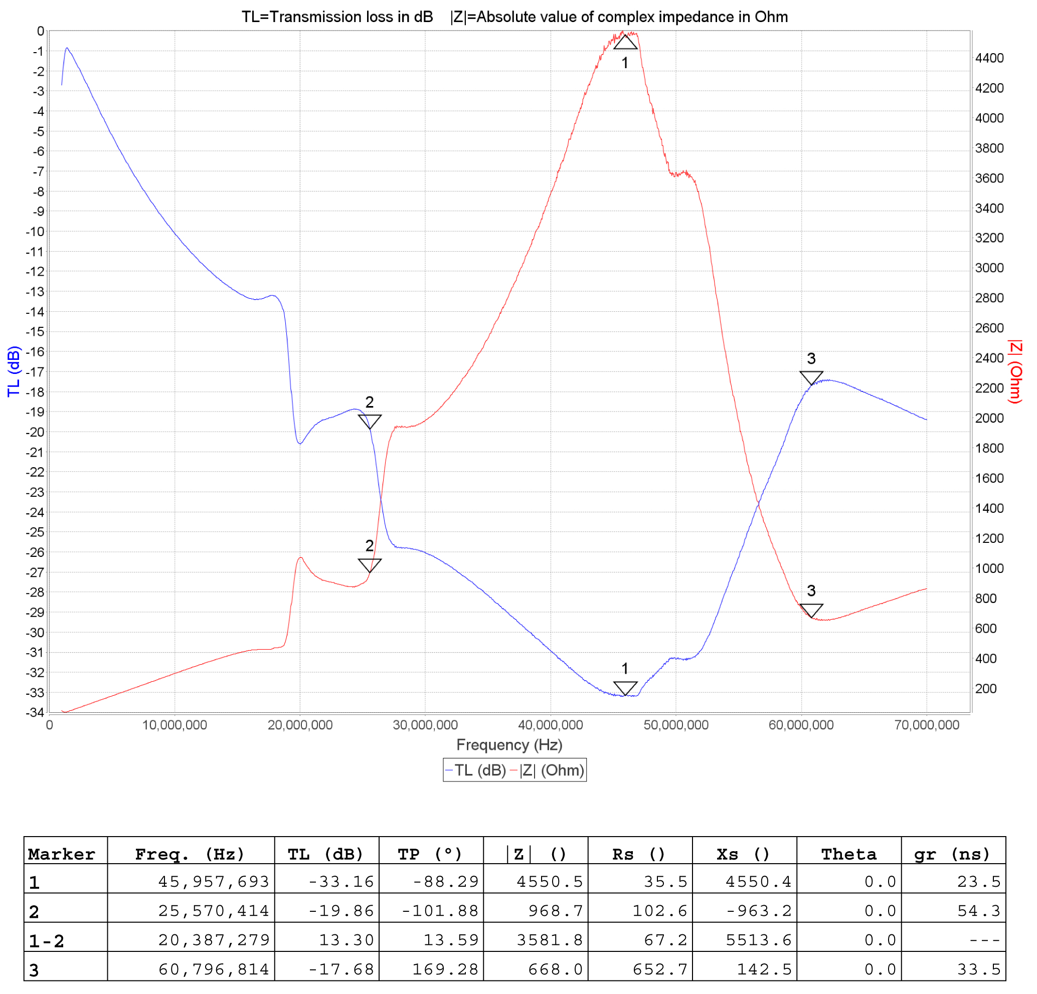
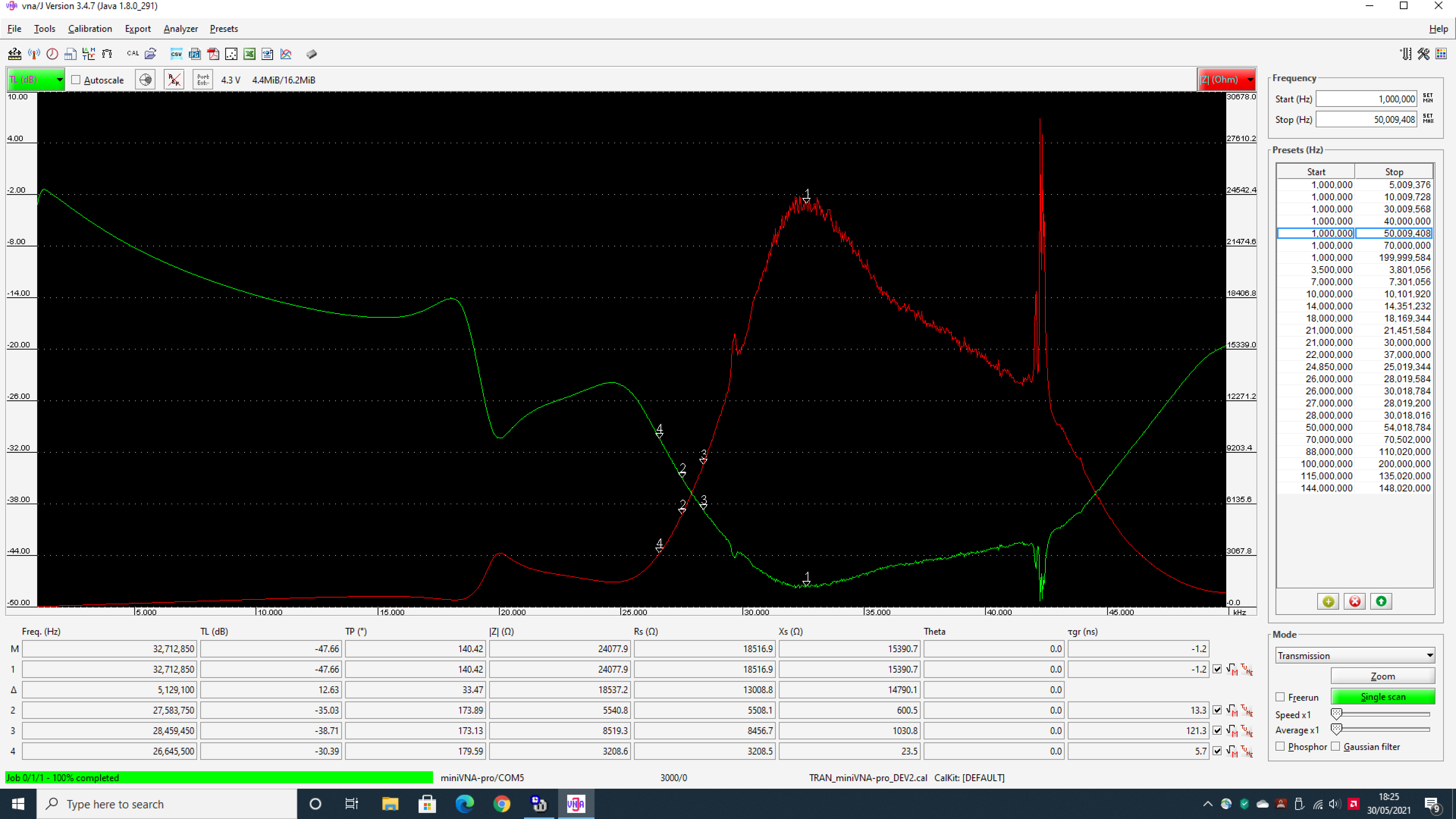
For starters, some info online suggested a 1/4 wave length of coax would be good for a choke. Based on this info, I cut a 1/4 wavelength of RG8 Mini which included the velocity factor. This turned out to be quite wrong as the VNA plot gave a a narrow banded choke [expected] – but peaking at around 46MHz. So – our coax was far too short – and by a long way. See the VNA plot below.
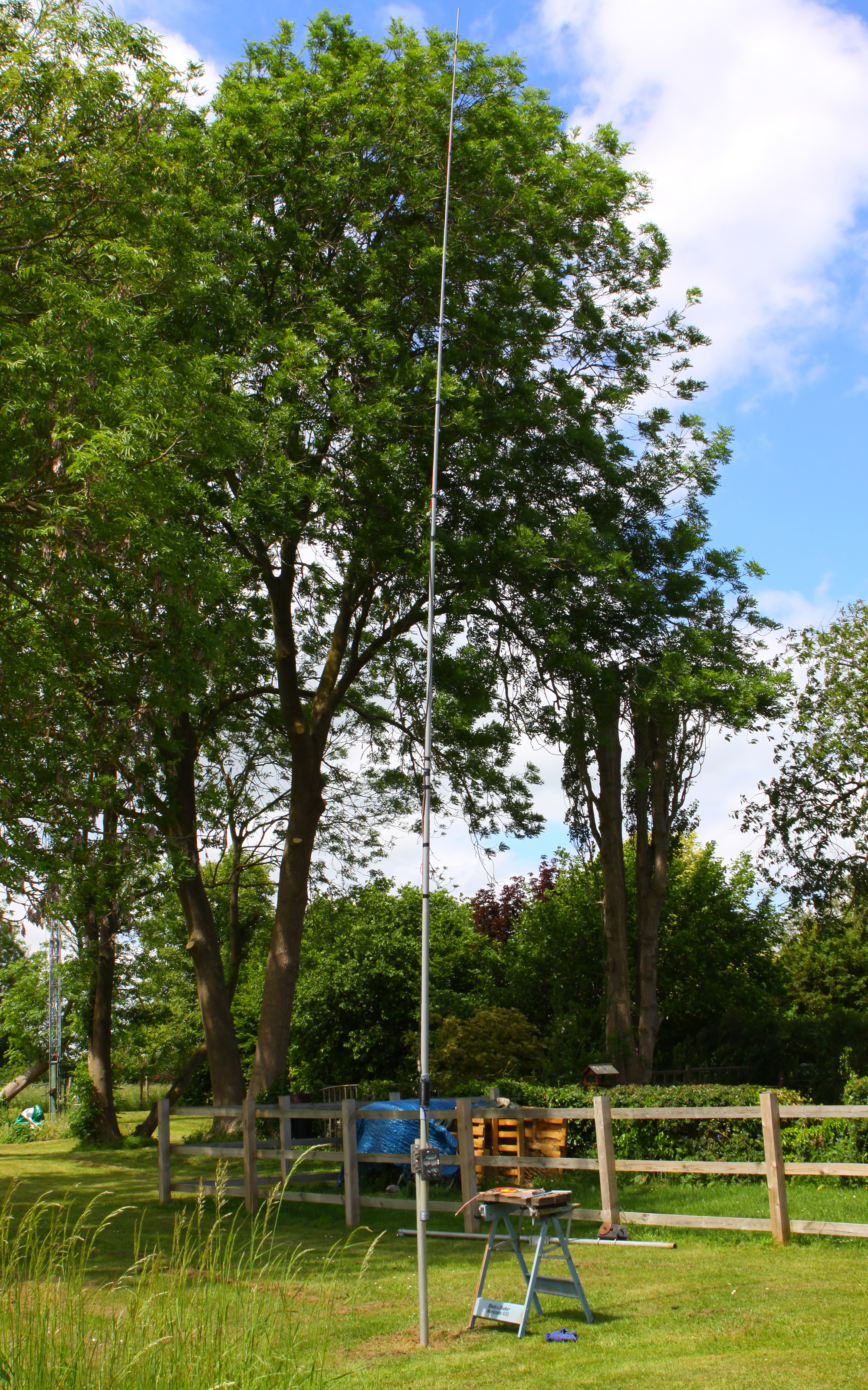
So, with the very lengthy intro out of way – let’s build our own version of ‘Sirio’s Gain-Master’. We obviously can’t call it the ‘Gain-Master’ as there’s a ‘Pat Pending’ and it’s the intellectual property of SIRIO antenne s.r.l [Italy]. We’ll call our homebrew version the ‘Q-Master’ – as we said earlier on, there’s no magic or Voodoo here, just a capacitor and coaxial Q-section doing the matching – same as the original Vortex Q64. I’ll also build our version of the original 5/8ths wave Gain-Master rather than the new 1/2 wave variant.
Build Your Own ‘Q-Master’ – a QRO 5/8ths Wave Sirio GM Clone on Steroids by Q82.uk
So, for starters we built our own choke. Some nice respectable figures with a choking impedance of over 5500 ohms were obtained at 27.500MHz and over 8500 Ohms at 28.450MHz. The choke was made by wrapping 20 turns of RG8 Mini around a 2 inch diameter fibreglass former. We used this former as the fibreglass fitted neatly over a ‘DX-Wire’ 10m mast which we were using purely as our test mast. If you don’t have fibreglass then a PVC former will suit. Figures won’t be too much different to notice any change in performance.
Constructors will also note that we’re using RG8 Mini rather the RG58. At best, RG58 will only really handle a few hundred watts before is starts creaking under duress. The Q-Master here should handle well over 1kw with ease. Our test unit handled 1500w key-down for 3 minutes without any issue.
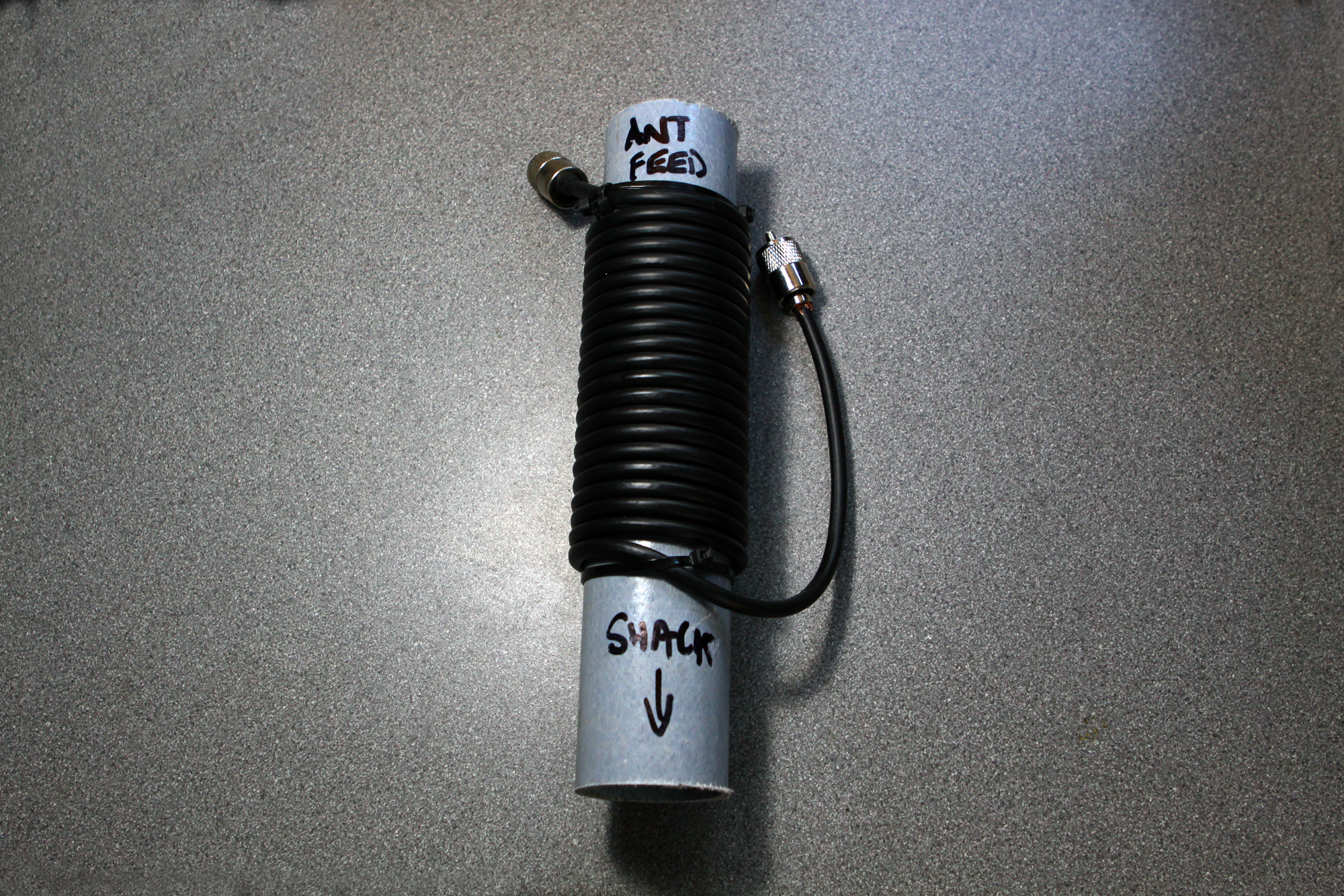
I’ll point out now, the Q-Master coax, wires and capacitor were temporarily tapped to the outer part of the mast. For a more permanent solution uses will need to look at other masts as the wire and capacitor ideally should be housed within the pole to prevent water de-tuning the antenna when wet. Masts such as those sold by DXCommander look more suitable for a permanent affair. For purely testing and evaluation – the DXWire.de 10m telescopic mast which we purchased from SOTABeams did a good job. Plus I’ve used this before on various IOTA activations and it packs down to a very neat 67cms so can be carried easily within a travel case.
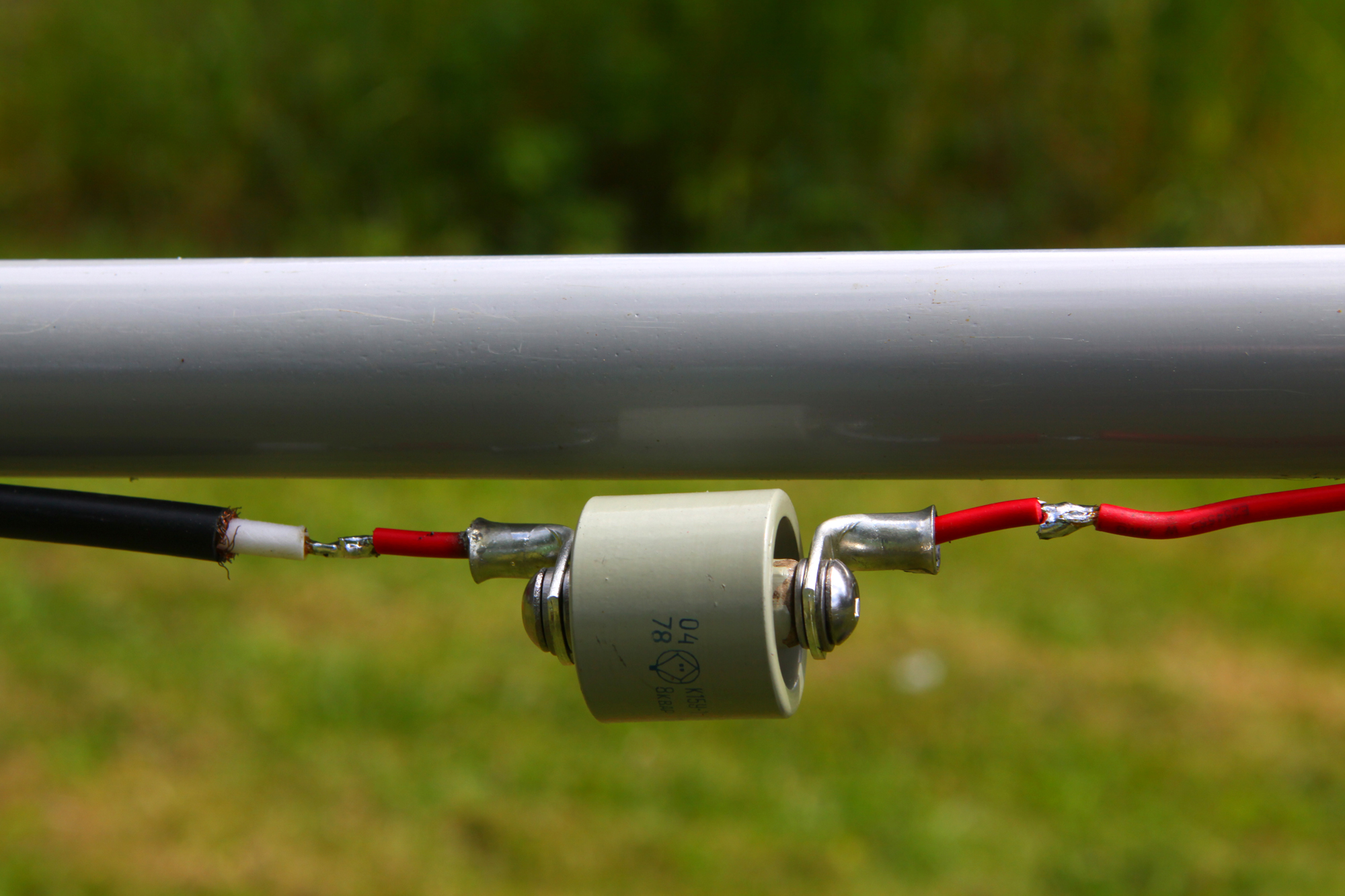
Dump that Coaxial Upper Capacitor.
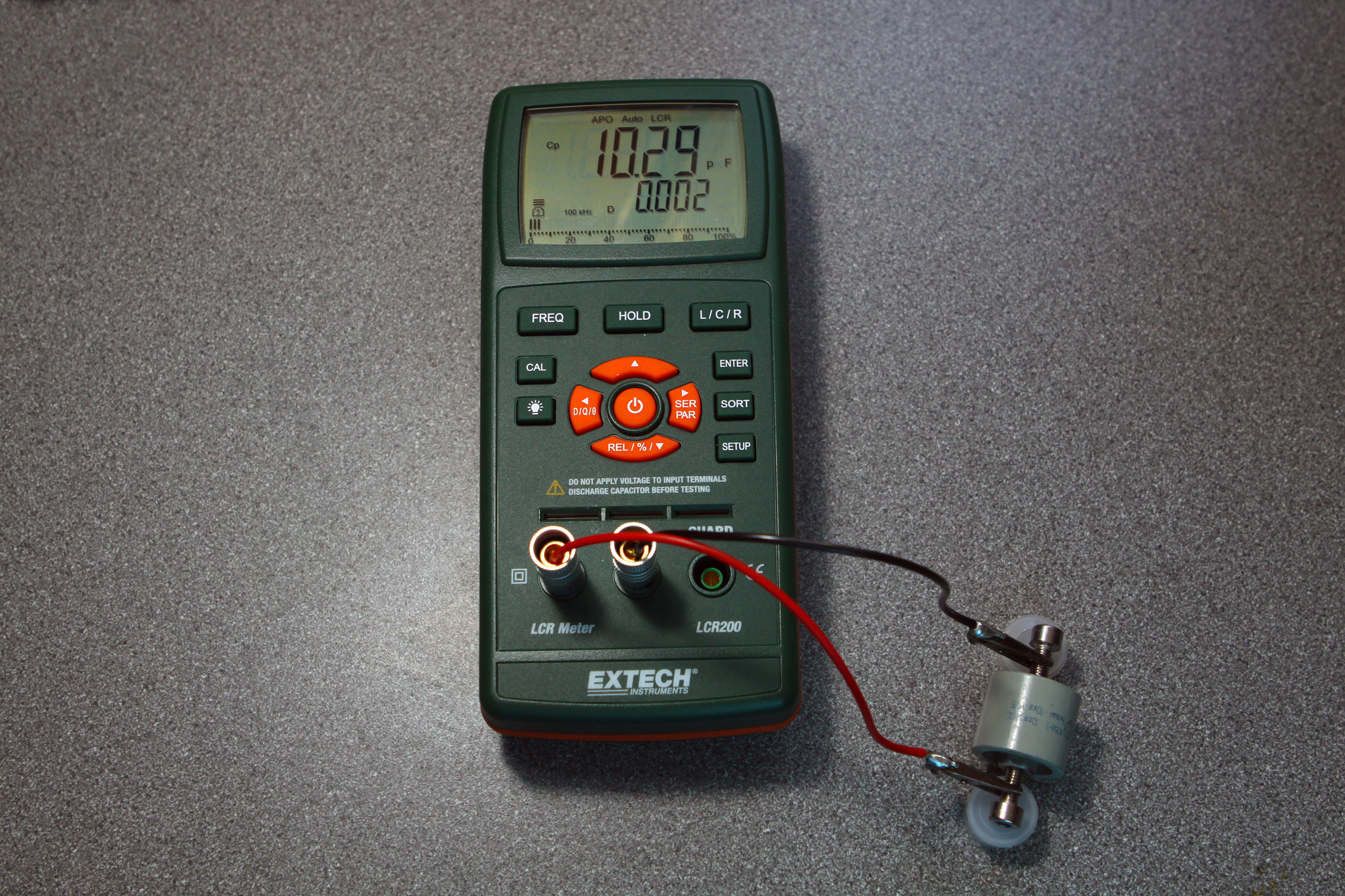
Stick a 10kv cold-war Russian 10pf in it – It will cruise at over 5kw. A while ago I found a heap of 10pf Russian military doorknob caps. Actually, I was using these for something totally different [my QRO 10Kw 6-way HF switch], but on stumbling on the idea that everyone wants a multi-kilowatt cheap ‘Gainmaster’ clone, these $5 odd-job caps looks like they could fulfil a useful purpose.
I don’t know a huge amount about them, but they are still frequently around on eBay. 10pf is pretty close when it comes to matching a GM. I had a choice of 5 in the workshop. When I measured them, most were around 10.29pf so pretty good and within a tolerance of 3%. Pretty good really when the advertised tolerance was +/- 10%
So – how did we get on?
Well the first test was a disaster. I left the ‘Q’ section [or the matching section of RG142 coax OPEN at the far end] and an analyser sweep showed all readings were way out [and by a long way]. Sometimes you know when there’s a [fundamental error]. If readings are really so far off – then normally physics is letting you know the fact and it’s time to check things over and correct the error.
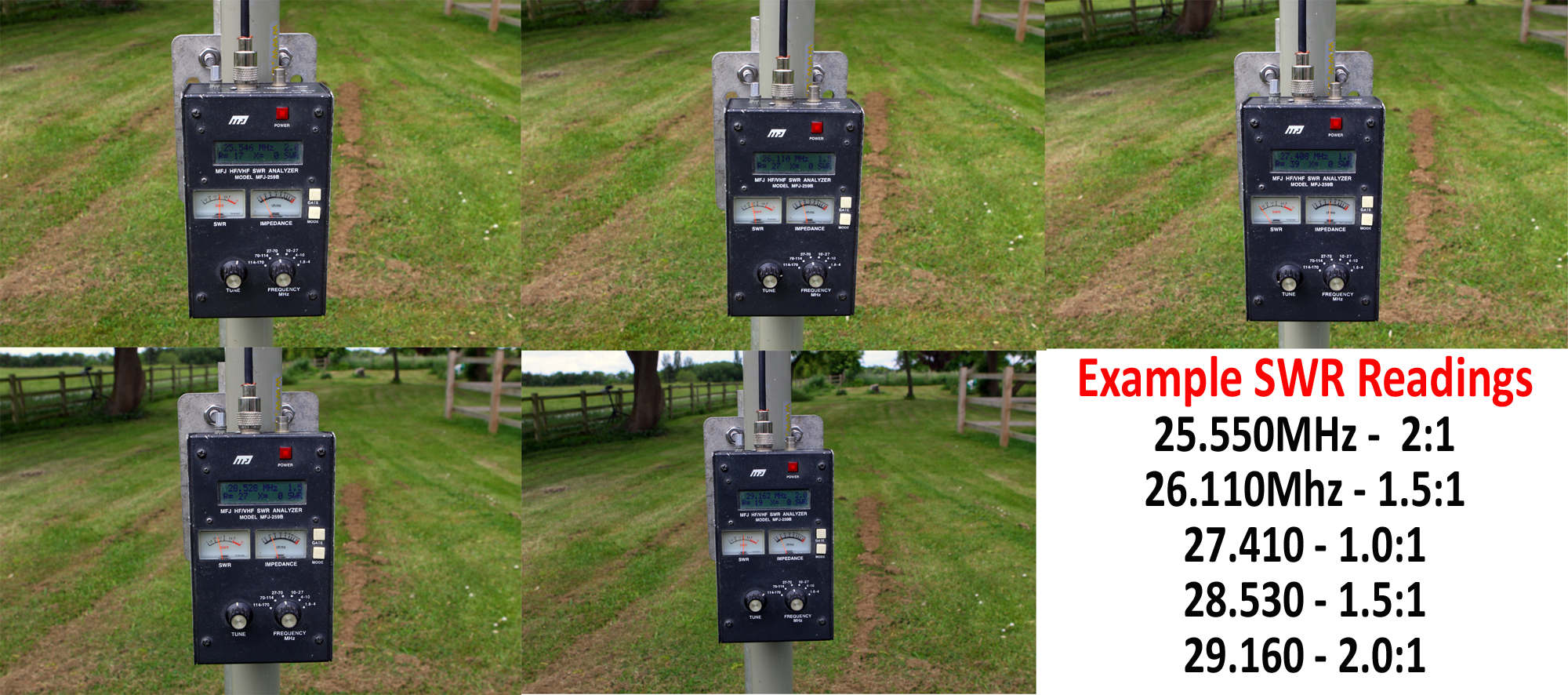
So – with the stupid [user error] identified, another analyser sweep was performed. Much better this time and a wide [3.1MHz+] bandwidth observed. After some minor trimming and adjustments, we obtained a very nice curve of around 3.6MHz. [Still not approaching the Vortex/G0UIH Q82MK2 though at nearly 4.4MHz and with substantially less gain!!].
See the analyser readings below [click for larger image].
See the data PDF below on how to build your own ‘Q-Master’ vertical that has already been tested at 1.5kw key down. There’s also images further down the article that may assist the constructor. Building is fairly straightforward although we’d advise that although we built our own version using a fibreglass pole, all components were temporarily taped to the [OUTSIDE] of the mast – purely for evaluation purposes. With any real-world build, the builder should aim to enclose everything [apart from the RF choke] in an internal weatherproof structure.
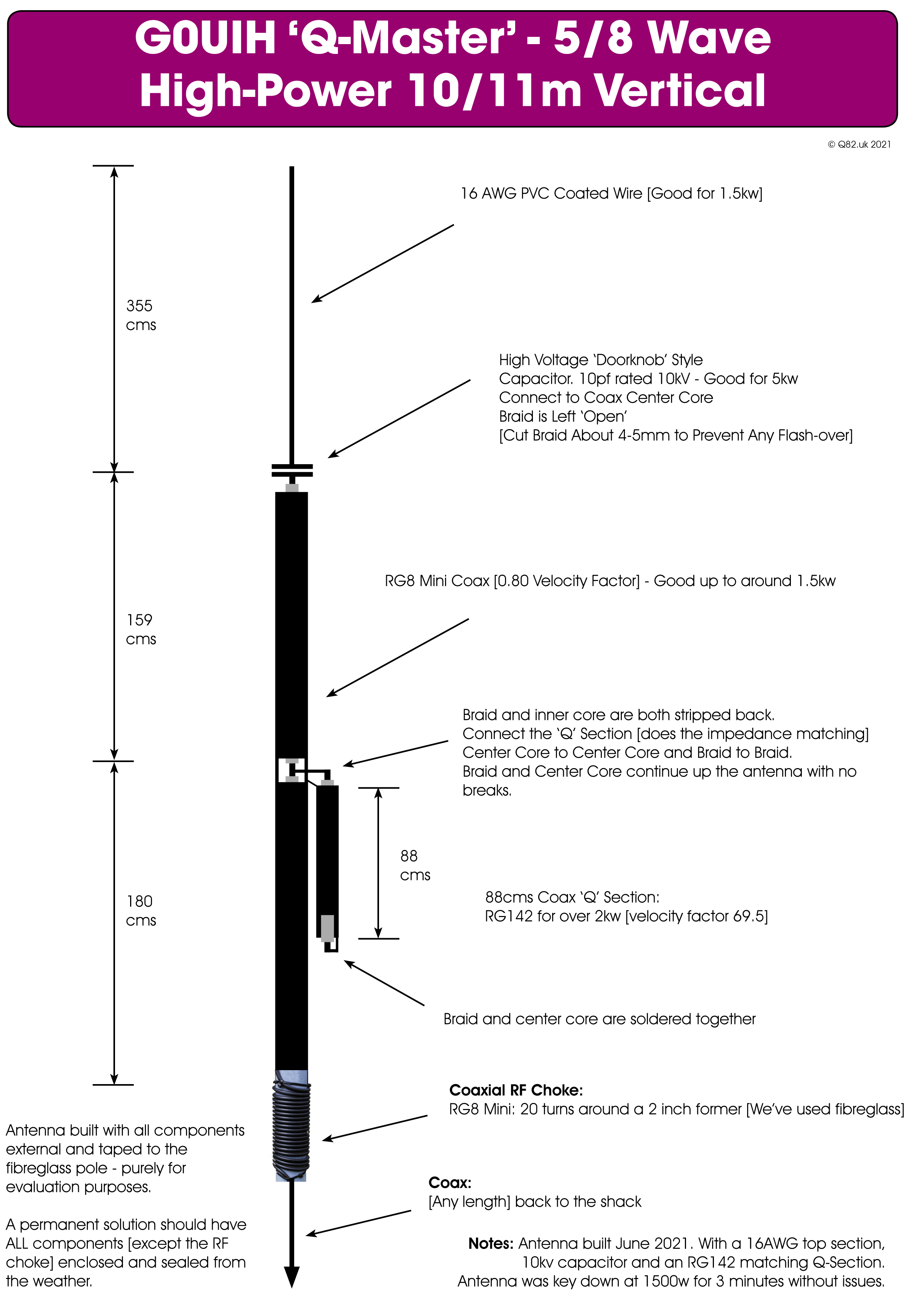
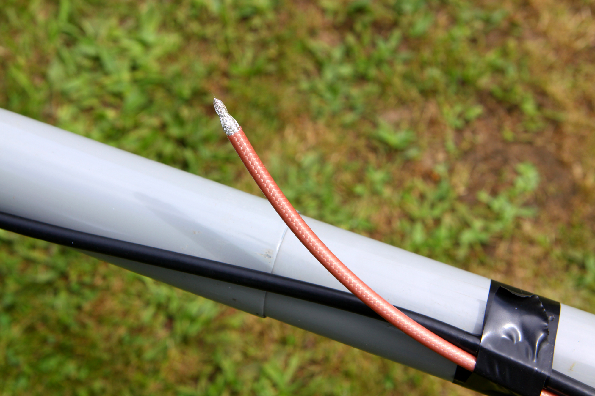
Make sure you solder the braid and inner core together at the base of the matching section and then seal.
Do You Want Even More Power Handling [up to 5kw?]
If you want more than 1.5kw handling, then there’s no reason why you couldn’t substitute the RG8 Mini for another quality coax [such as ‘Westflex 103’] for example. When using ‘Westflex 103’, the velocity factor is 0.81 rather than 0.69 so the Q-Section length will change. We estimate that it will be about 96-97 cms in length although we’ve not tried a real build yet with this stock. The vertical lengths will also differ as will the choke.
We plan to do real 5kw ‘Live Build’ using Westflex 103 at some point in 2023 for all QRO aficionados so stay tuned! Everything will be published here on Q82.uk
The ‘Small Print’ and Legal Mumbo Jumbo:
‘Gain-Master’ is a ‘Pat Pending’ [according to SIRIO] and has been for over 10 years [not much movement then!] and all references are the intellectual property of SIRIO antenne s.r.l [Italy]. Use on Q82.uk is merely for hobby reference only.

