
Limitations of Coaxial Air-Cored Balun Chokes
If you’re reading this, then you are probably familiar with the ubiquitous ‘Ugly Balun’ which seems to have cropped in in nearly everyone’s ham shack and antenna setups. The ‘Balun’ is not really a balun at all, more so being an RF choke that prevents common-mode currents [currents that flow on the braid of the coax]. There’s no impedance transformation going on and when you look at it, it looks like a coiled-up piece of coax.
The balun is the simplest form of construction. Coaxial cable wound around a former. This can be wound around a former such as a fibreglass tube. Additionally, the coax could be wrapped with the cable ‘side-by-side’ and secured with something like cable ties. In this application there’s no former as such, and the dielectric [internal space] used is air. They are often called ‘Air Wound Chokes’.
Just ‘Google’ it and there’s a plethora of data – but take some of it with a ‘pinch-of-salt’ as they say.
You can’t just throw a heap of coiled coax together in the hope that it will magically work. There’s some physics behind it all. Variables such as type of coax, the ‘former’ used [it could be PVC, fibreglass or ‘Air’ for example], the diameter of the former and the length of the coil also play a role so there’s 4 key ‘Variables’ at work here. One can effect the other 3 so it’s not all plain sailing. Read on and build yourself an air-core choke that works. The cost is only the coax and a former if you decide to use one. We’ll even give you all the data.
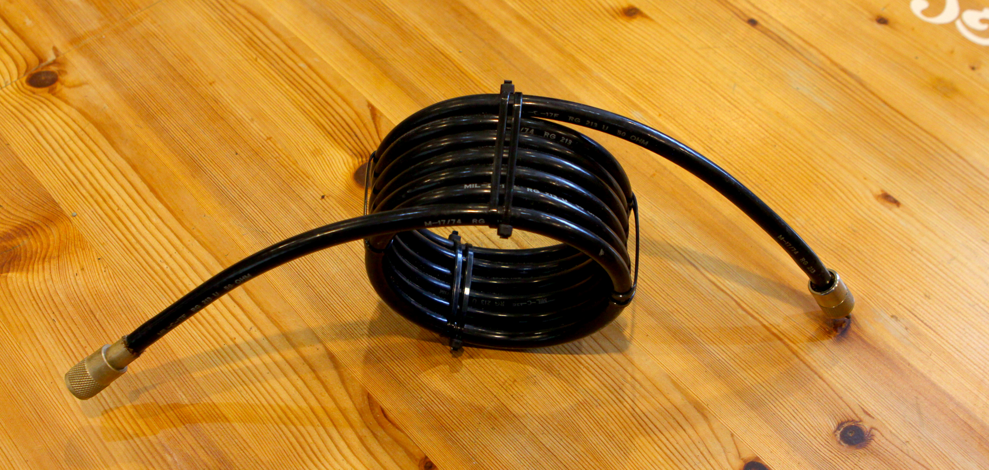
19 turns on what looks to be a 3 inch former. We’d say good for the 20m band
To many hams, the idea of a ‘Balun’ or ‘Choke’ on their antenna seems to install a huge confidence boost that its going to help them ‘Get-Out’ or do something magical with their set up. But do they [Really] know what this coiled up piece of ‘Voodoo’ coax does and what the theory is behind it?
In simple terms, the ‘Coil’ presents a high impedance [Hi-Z] at the feed point which should prevent common-mode currents flowing back down your coax to the shack. RF generally doesn’t like flowing down High-Z paths, preferring a Low-Z route instead. The coil of coax [Choke] presents a High-Z block typically at the feed point of an antenna [A Yagi beam for example], or at the base of a vertical antenna. The reduction of these currents can help prevent RF radiation and interference in the shack.
Let’s take a typical Yagi beam, say a 3-element mono-bander for 20m. Actually, the number of elements is not really relevant. Users could potentially fit a ferrite-core balun. Ferrites are nice and wideband but of course more expensive. Wrapping 12 turns of RG303 coax around a type 43 Core [a 240-43 core would be a good typical example] could give up to 8000 ohms [8k] of choking impedance at 14MHz. For those wanting to know more, the bare minimum choking impedance required for a choke to actually ‘work’ is 10 times the load impedance. As we are talking of 50 ohm loads, then 500 ohms is the absolute minimum although some purists would say this really isn’t enough and would point to choking impedances greater than 1000 ohms [1k] to become effective.
So, if we wanted to construct a simple ‘Air’ choke [and given the examples from the info below], we could probably use about 15 turns of RG213 on a 4.25 inch former. That should put us in the right ‘Green’ area. From G3TXQ’s graphics, there’s plenty of choice although eagled eyed readers will see that ferrite chokes are inherently more broad-banded than the ‘Air’ choke. On the flip side, coiled coax costs the operator very little and you don’t have to purchase expensive ferrites. It’s a bit of a swings ‘n roundabouts affair for sure!
Steve Hunt [G3TXQ] [sk] produced some graphics showing the choking impedance of both air wound cores and ferrites. Although sadly Steve is not with us anymore, his site is still active and users can see the original graphs what are the optimum solutions. http://www.karinya.net/g3txq/chokes/
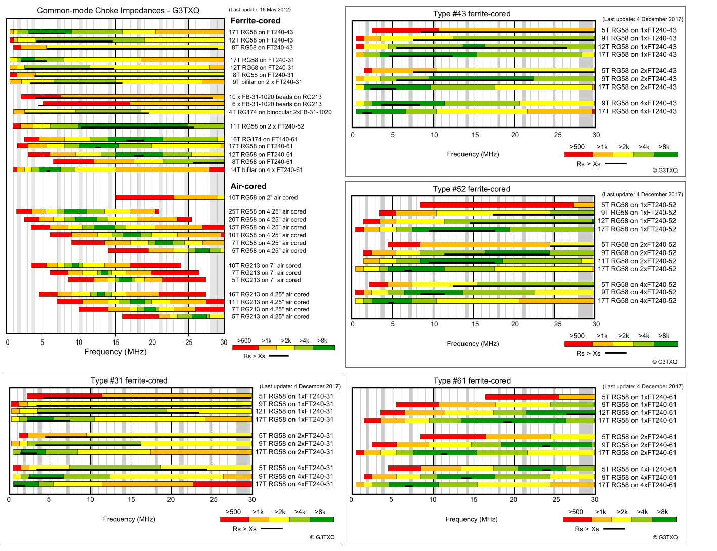
You should aim to build chokes that are at a minimum in the ‘Yellow’ band [Over 2000 ohms]. Chokes that are performing better are in the ‘Light Green’ bands which give a very good choking impedance of up to and over 4000 ohms [4k]. Chokes that are optimum are shown in ‘Dark Green’. This shows a choking impedance of up to and over 8000 ohms [8k] and are extremely efficient. Chokes shown in ‘Amber’ are adequate [although not optimum] but should work if you don’t have too much in the way of common mode currents. Chokes shown in ‘Red‘ should be avoided.
We have shown some combined images of Steve’s graphs above. Images are copyright of Steve Hunt G3TXQ www.karinya.net
More out of curiosity during lockdown, I built one of the chokes that G3TXQ had performed some previous VNA measurements on and it was no surprise that my 10/11m air-core choke using 6 turns of RG213 MIL on a 4.25 inch air-former pretty well matched Steve Hunt’s figures. Our stock was ‘RG213 MIL‘ so there is a minor variation in the stock used. Here’s our own VNA plot below [Click to see a hi-res PDF].
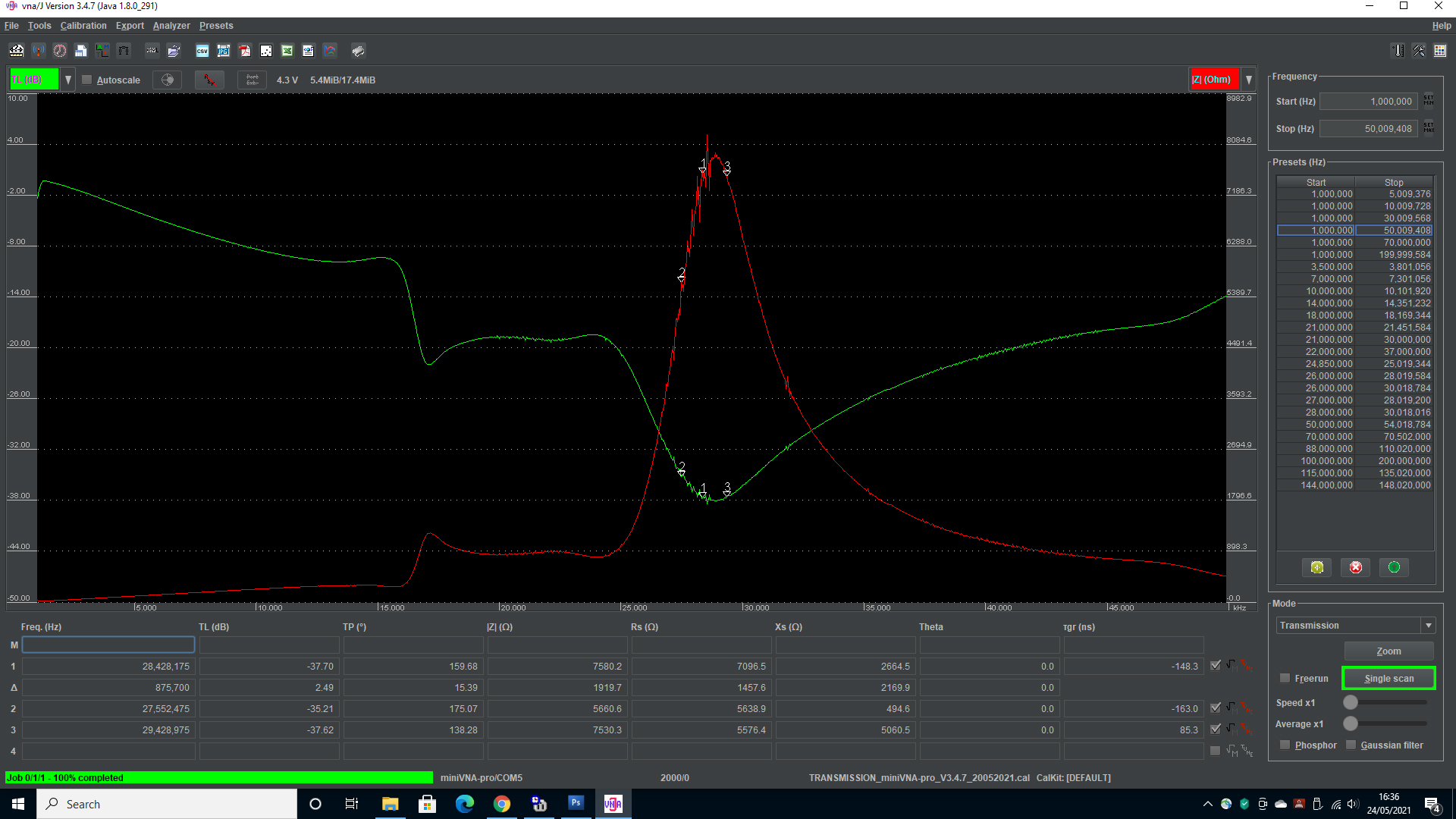
As you can see, air-core chokes [rather than ferrites] are quite narrow-banded in comparison. Saying that, when tuned correctly, they work extremely well for monoband solutions and are cheap and easy to construct. They are NOT really suited for multi-band operation. G3TXQ’s experimentation uses mainly RG58 and RG213. We have produced results using much more suited modern coax.
In most shacks, you won’t be using RG58. It’s cheap and nasty stuff and best avoided. G3TXQ also quoted chokes based on the thicker RG213. Again – this is quite ‘old skool’ coax – so we will look at a radom choke and figures based around a more modern premium example such as
Formula Zero Super Low Loss Coax which is very similar in specs to Westflex W103.
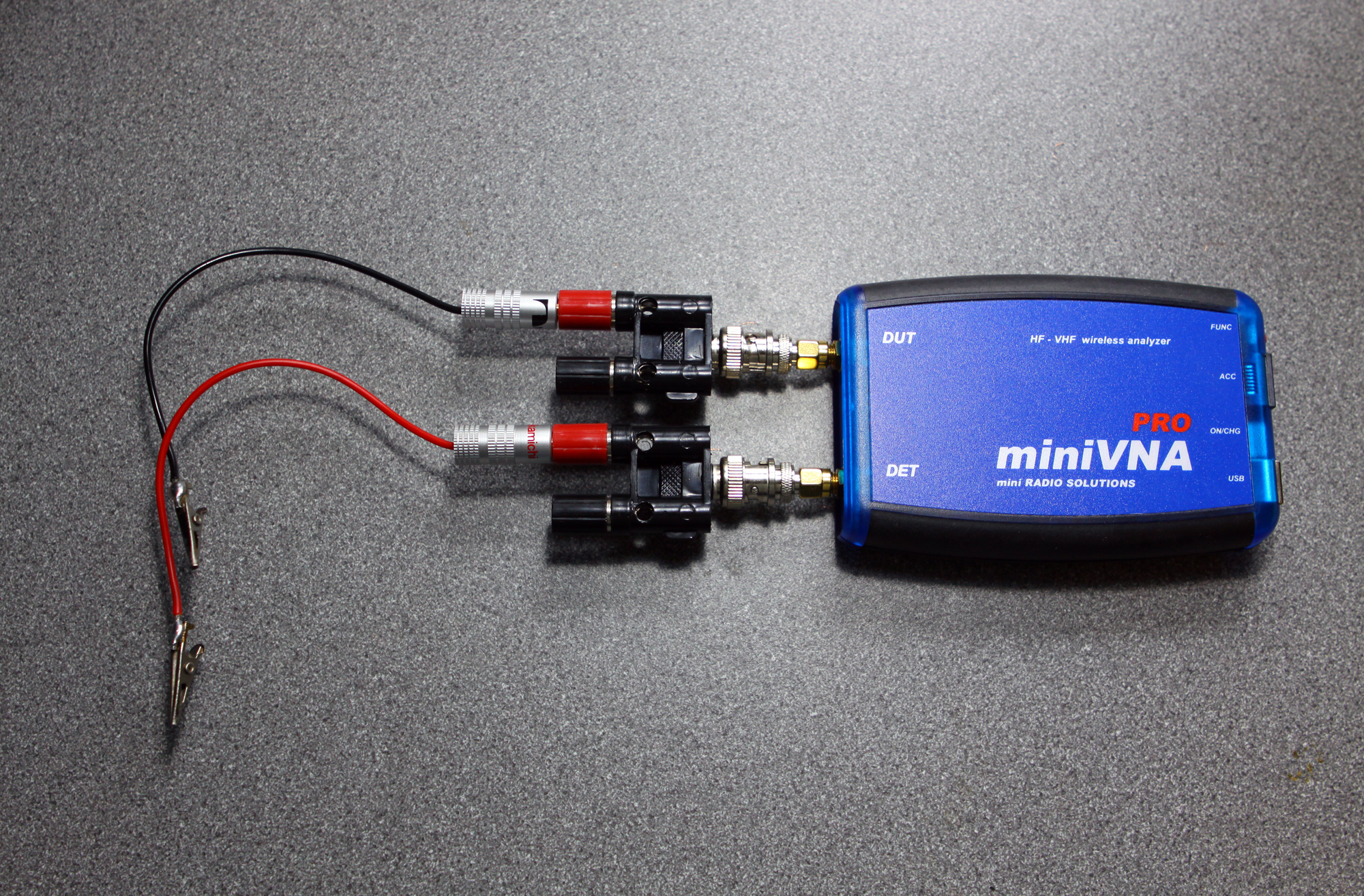
On the test bench here at Q82.uk we have a Mini Radio Solutions [MRS] Mini VNA Pro. This little USB VNA has 2 port capabilities up to VHF. Have a look at the various screen grabs and also our graphs showing the choking impedance on ‘Formula Zero’.
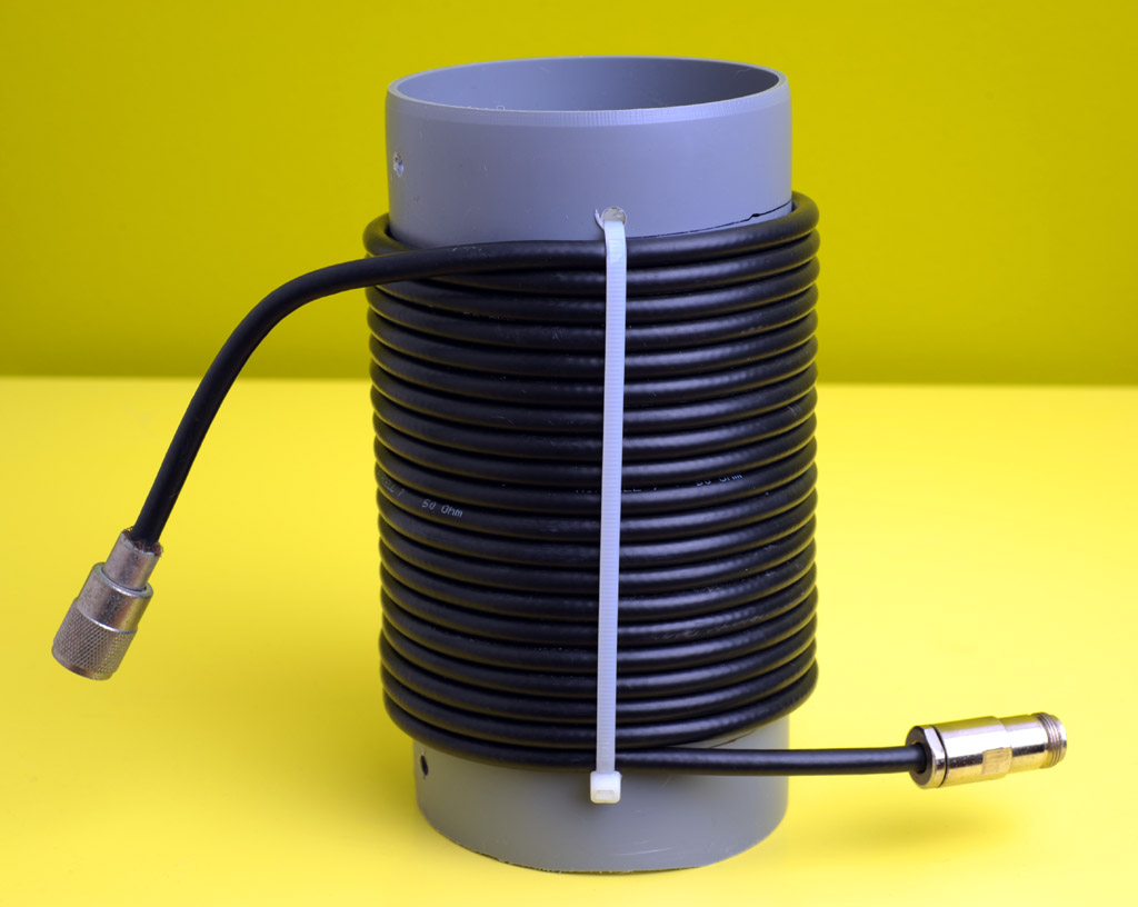
See our VNA evaluation plot below based on 5.5 turns around a 20cms [7.87 inch] former. This choke was just a random selection of coax wound around the first large tin [used as a former] found in the workshop. The plot was run between 0 and 30MHz and shows a shows a peak at around 17.200 MHz of about 2300 ohms choking impedance [which is not optimised].
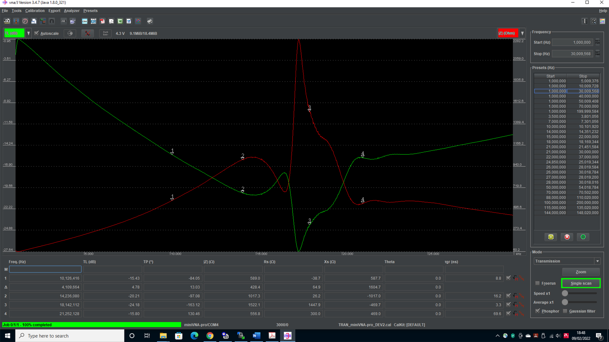
It’s not an ideal choke, but shows how a VNA helps constructors make chokes for a certain purposes. In real terms, this choke could be used on 17m. Saying that, a smaller diameter former with more turns would yield much better results. This exercise merely shows how the VNA is an invaluable tool in the workshop.
As with most air chokes, they tend to be quite narrow banded. This is confirmed on the VNA as the choking impedance drops off quite dramatically either side of the ‘peak’. What isn’t showed is the huge narrowband peak at around 77MHz of around 5000 ohms and another smaller peak at around 140MHz – so it’s a ‘swings and roundabouts’ affair requiring some experimentation.
In Summary – Air Core Chokes:
Pros: Cheap with no costly ferrites. You need only a length of coax and a couple of plugs.
No enclosure required and virtually no loss or heating of the coil. High choking impedance at resonance.
Cons: Can be narrow-banded when compared to ferrite. Not optimum for multiband solutions although with the right test gear, you can get good results across more than one band.
You really need some kind of test equipment [i.e. VNA] to accurately measure the ‘peak’

