A ‘No-Brainer’? Reducing the Size of Your Dipole By 33% By Constructing it From Coax
It’s been said many a time – there’s no such thing as a free lunch. The same comes into play with coaxial antennas, especially those constructed of 0.66 velocity factor coax such as RG58 and RG8.
The coaxial antenna, in particular the coaxial dipole when wired in a particular fashion, has been flaunted as being an antenna with an interesting proposition of having a substantial size reduction [the coax velocity factor is mentioned as the culprit – but more on that later] – so on the face of it, this should be a real winner yes? [Well not quite….read on]
For our exercise, we’ll use the 20m band as a reference. It’s a band where a size reduction could be useful to operators who have a small garden. A plot that won’t fit a 33 feet dipole in but [will] fit 23 feet looks to be a good solid move.
Sounds useful doesn’t it. Any installation that saves space is surely a winner. Just think of it, this could be a real game-changer when we start talking about the lower HF bands such as 40, 60, 80 and 160m. You could save oodles of space.
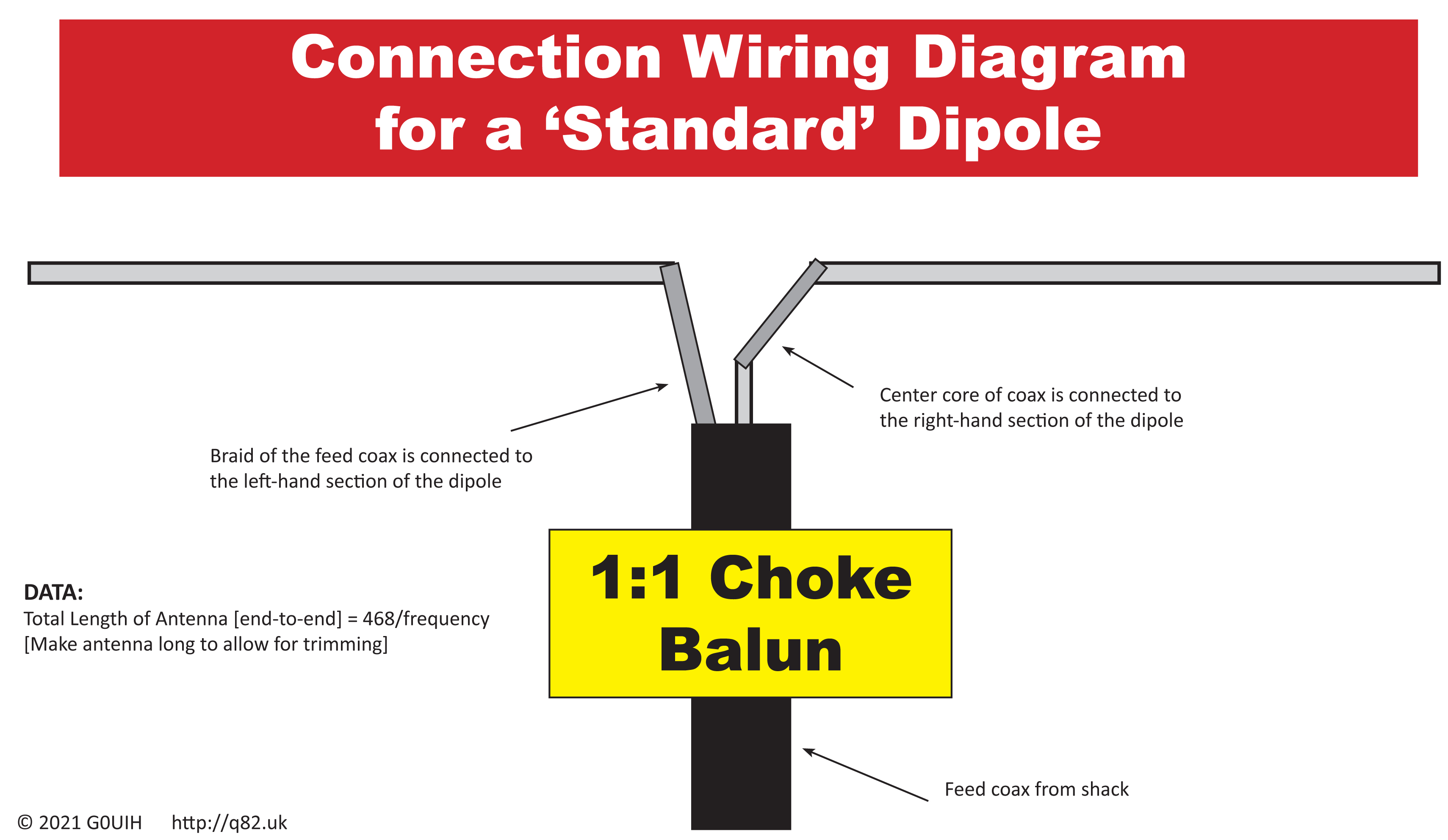
So, before we go further and jump for joy, let’s go back to basics. The ‘Standard’ basic dipole. 2 wires each, both a quarter wave in length, connected with a coax feeder at the centre. You can’t really get much simpler.
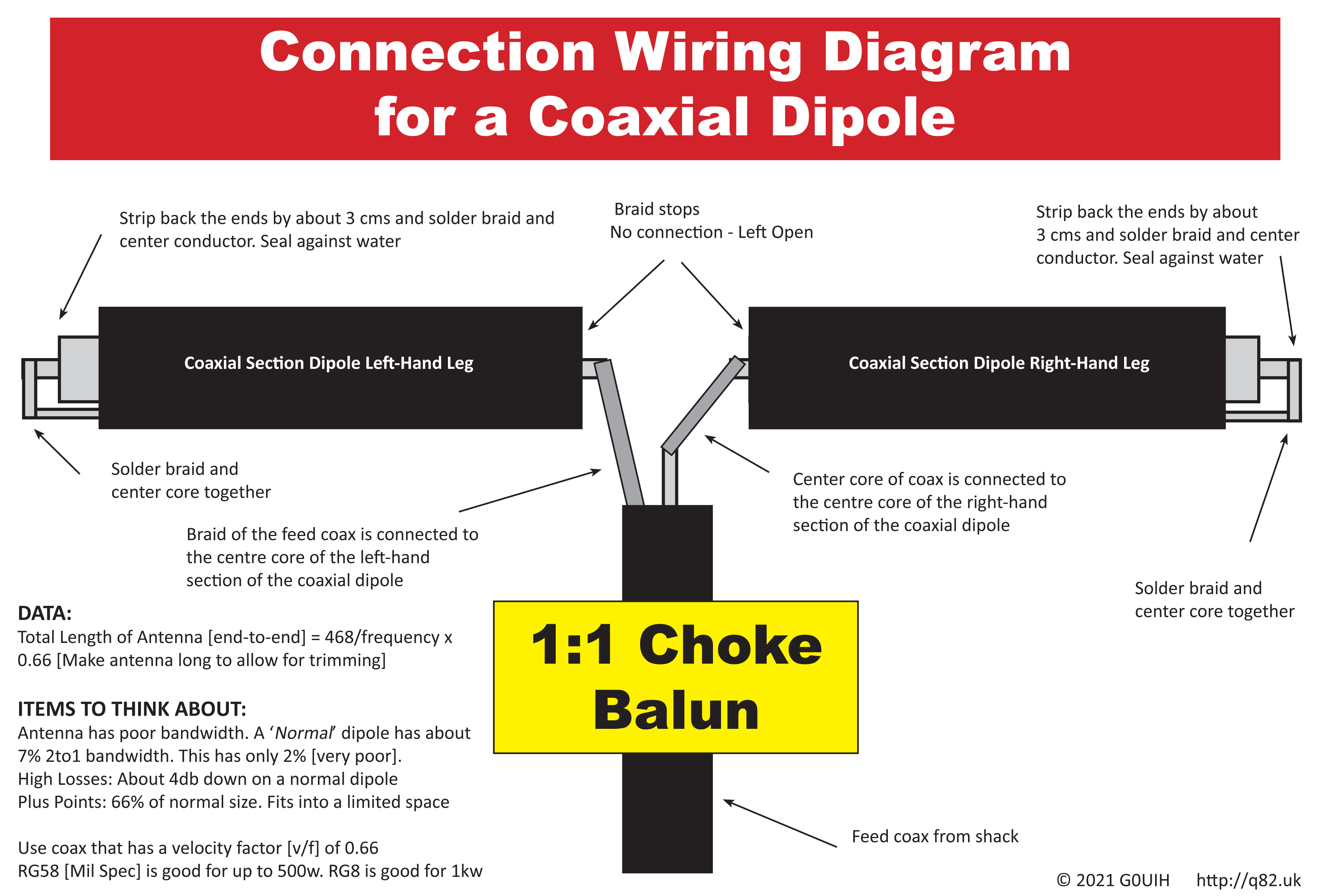
From the standard dipole, we move to our coaxial dipole shown below. Some of the online data that’s doing the rounds, suggests that the velocity factor of the coax is the reason why we can shorten the antenna. But look more closely at the arrangement, especially the ends where the braid is soldered to the inner conductor. What we see here, rather than the coax doing any magical work, is that we see a ‘Linear Loaded‘ stub in action. Normally, linear loading will be a small amount of loading used to reduce the length of an element. What we see here, is a large amount of loading [the extended length of the braid acts as the loading] as it comes back towards the feed-point.
As mentioned originally, this antenna has just one plus point. If you construct it using 0.66 velocity factor coaxial cable [such as RG8 or RG58 MIL] then you can reduce the overall size by about a third. It’s a big plus when you have a challenging situation with regards to space. However, as we mentioned very early on – this antenna does have its downside. Bandwidth suffers very badly. You’ll only get about a third of the bandwidth that you would when using a normal ‘Standard’ dipole. If you can hack this, then just for good measure, the antenna is also about 4db down on the standard dipole.
So the ‘Free-Lunch’ scenario really hits home. Saying that, in some circumstances, some constructors could potentially find a use for it.
As a caveat if you do plan a build, don’t use coax that has a PTFE, Air-Spaced or Foam dielectric as this increases the velocity factor – and as such, will make the dipole longer than shown. Such cables often have a velocity factor [v/f] quite a bit higher; sometimes around 0.80 or even higher. You’d be better off doing just a normal dipole [or Double Bazooka] shown below.
We’ve put together a table below based on three methods of construction. The left-hand column shows a normal standard dipole constructed using 14AWG bare copper wire. Likewise, the same antenna using PVC coated wired wire is shown in the centre column. Note the PVC coating affects the overall velocity factor and reduces is slightly – hence the shorter lengths. Taking things to the extreme, the coax dipole length are shown in the right-hand column
| Bands | *14 AWG Bare Copper Wire | *14 AWG PVC Coated Copper Wire | 0.66 v/f Coax Dipole |
| 10m | 509 cms [5.09m] | 486 cms [4.86m] | 336 cms [3.36m] |
| 11m | 528 cms [5.28m] | 506 cms [5.06m] | 348 cms [3.48m] |
| 12m | 584 cms [5.84m] | 560 cms [5.60m] | 385 cms [3.85m] |
| 15m | 680 cms [6.80m] | 654 cms [6.54m] | 449 cms [4.49m] |
| 17m | 823 cms [8.23m] | 770 cms [7.70m] | 543 cms [5.43m] |
| 20m | 1068 cms [10.68m] | 1040 cms [10.40m] | 705 cms [7.05m] |
| 30m | 1432 cms [14.32m] | 1380 cms [13.80m] | 945 cms [9.45m] |
| 40m | 2024 cms [20.24m] | 1960 cms [19.60m] | 1336 cms [13.36m] |
| 60m | 2708 cms [27.08m] | 2620 cms [26.20m] | 1787 cms [17.87m] |
| 80m | 3800 cms [38.0m] | 3704 cms [37.04m] | 2508 cms [25.08m] |
| 160m | 7800 cms [78.0m] | 7600 cms [76.0m] | 5148 cms [51.48m] |
From the above table, if you operated on 80m – then length or your dipole would only be just over 25m using 0.66 v/f coax compared to 38m using bare wire. A really big worthwhile saving in space but you’d take a real hit in bandwidth and performance..
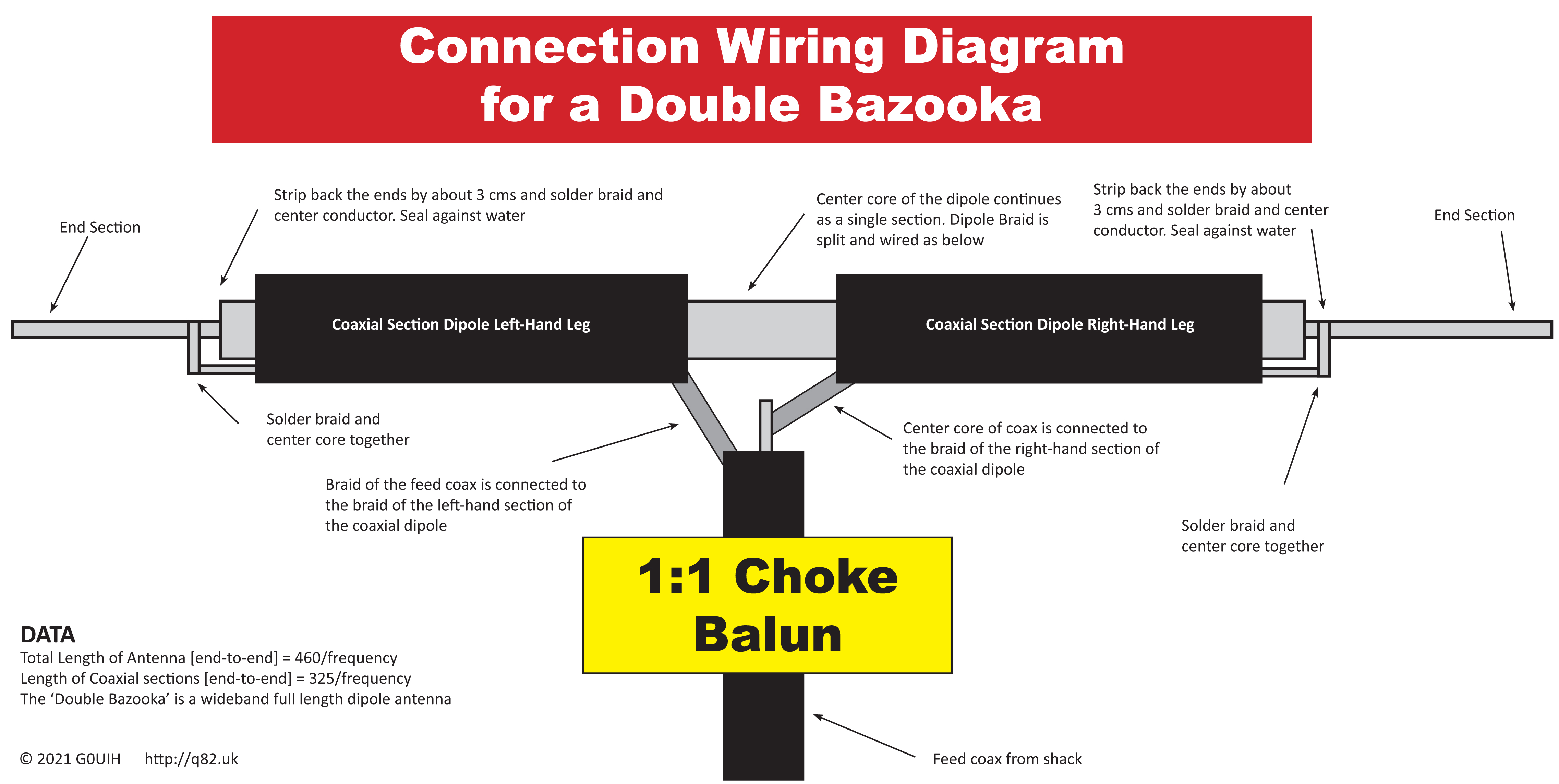
As on off-shoot, there seems to be be some confusion [especially when you look online] in that some site owners seem to mix up coaxial dipoles and ‘Double Bazooka’ antennas. There’s plenty of really bad [and wrong] advice out there. Here’s the ‘DB’ antenna. As you can see, the wiring is totally different. A search also reveals a designer who uses a length of 0.66 v/f coax as a reflector on a Yagi . It’s an interesting thought but I’m intrigued to see how the 0.66 v/f can work in this situation.
For all the illustrations on this page – just click on each one to download a hi-res PDF