
Build a 6.6dBi 5/8th over 5/8th over 5/8th Wave
2m Collinear 1Kw+ VHF Vertical That Will Last.
This is a long article 🙂
We’ve all bought one [well most of us]. The ‘White-Stick’ VHF and UHF verticals that plague nearly every ham radio outlet from here to Timbuktu. It wouldn’t be so bad, but they never seem to last. I’ve had three of varying guises and advertised by different manufacturers. In all, I must have spent the best part of £450 and ended up with three heaps of scrap. For the main, the majority seem to have been conceived from the same hardware factory as the faults that affect one, also affect others. There seems to be a couple of exceptions. That’s ‘Diamond‘ and ‘Comet’. These look [although I can’t be certain], to be their own manufacturing as there are distinct differences.
One main issue with the ‘White-Sticks‘ is their apt inability to retain the radials. Give them a season of bad windy weather and you’ll be guaranteed that one [if not more] of the radials are lying on the ground. Inspection will show you how NOT to manufacturer a ground plane radial system.
For starters, we have a threaded stainless bar that ‘screws’ into a tapped aluminium base and held by a stainless nut. Alarm bells are ringing straight away with those in the know. Hard stainless-steel rods threaded into a much softer aluminium alloy is a recipe for early failure. Constant wind and vibration slowly causes the gap between the threads to expand as the stainless effectively ‘Cuts’ easily into the aluminium. As the gap increases, the radials begin the flex further. Once it starts – then it’s game over. I lost my first one after one bad winter.
Both metals are also dissimilar which causes galvanic corrosion. This occurs when two dissimilar metals are electrically connected. One metal (the cathode) is protected – in our case the stainless steel, whilst the other (the Aluminium anode) is corroded. The rate of attack on the anode varies with the types of metals. Take a look further here on our article which goes into more detail.
As a finale to the white-stick, many have some form of matching capacitor in the base section to remove the unwanted reactance. These capacitors are generally low-grade ceramic discs and are not rated for any real RF output. Although I’ve seen some white-sticks rated at 300w, I can attest that my second white-stick burnt out with 75w on 2m. An examination showed a disintegrated ceramic disc cap.
The design here will easily handle 1kW+ as it has no electronic components as such. It’s limited only by the diameter of the wire from the feed socket, the feed socket itself and the ‘Gap’ between the ground plane and main radiator. Likewise the fibreglass gap between the phasing sections. A 1cm spacing will easily give isolation for 1Kw of RF.
So, with the intro out of the way – here’s my solution for a nice sturdy and heavy duty 2m ‘Triple 5/8th wave Collinear Vertical‘ with not a white stick in sight. I’ll mention from the start. It’s not a particularly easy, cheap or quick solution. If you’ve come for a quick cheap fix – then move on – I won’t waste your time. This project requires some dedication, time, a few tools and quite a lot of different hardware items.
It took me about 4 days to complete but that also included some additional experimentation and a few thrown away parts in the process to achieve what I wanted. You should be able to complete the job much sooner and without too much waste.
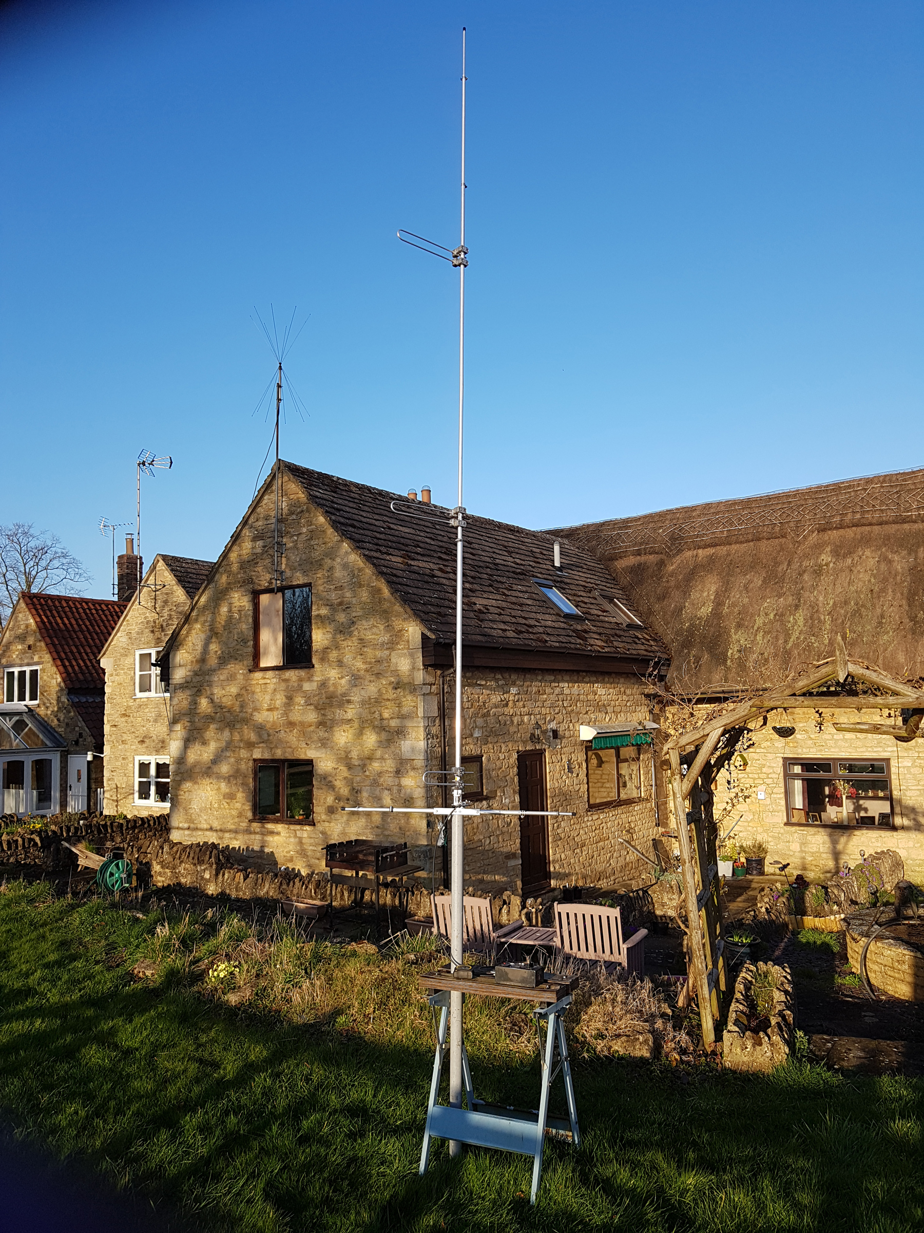
For the purists: I know the ‘thatch’ is looking a bit tatty. Our QTH is circa 1728 and we’ve a new re-thatch booked for 2022
List of Hardware
Before we get into the construction, here’s a rundown of what’s required in the hardware dept. In all, the cost of hardware will be in the region of £175 but many builders may well have some items already in their workshops – so this will help keep costs down further. Where appropriate, I’ve supplied links to various commercial outlets. Items such as aluminium tube and other hardware are not linked as they should be easily sourced. It may sound like you’re stretching the bank balance, but believe me – there’s nothing really to go wrong with this antenna. It’s extremely sturdy and has no ‘moving parts‘ or electronic components that have limitations and should last you years. At worst – it will only require a clean of the joints where clamps meet tubes. Then good to go again!!
With construction – I’ll highlight the ‘Important and Relevant‘ points – we’ll leave the rest up to your own ingenuity 🙂
TIP!! – Put 5 x M6 Washers into the top of each aluminium clamp hole as the nut will use this as a vertical spacer. Otherwise you won’t be able to tighten each nut fully
Base Mounting Plate:
• Aluminium Channel: 6 inch x 2 inch x 1/4 x 5/16ths [x 55cms in length]
• Clamps: 2 x Stauff Group 6 Heavy Duty Polyamide [Not Metallic!!] Isolating Clamps
• Base Mounting Plate U-Bolts: 2 x 1.5 inch M8 Stainless Steel
• You’ll need part numbers ‘6048.3PA‘ for a Scaffold Pole or ‘6050.8PA‘ if using a 2 inch pole
• Base Mounting Plate End Cap: 1 x Nylon Black Square Section Cap [1.25 inch]
Base Mounting:
• Aluminium Box Section: 1.25 inch x 1.25 inch x 10 Gauge wall [x 80cms in length]
• M8 x 45 Stainless Hex Bolts [x2] Washers/Nyloc Nuts
• M6 x 35 Stainless Button Bolts [x2] Washers/Nyloc Nuts
Radials:
• Aluminium Box Section: 25mm x 25mm x 2mm [2 x 25cms]
• Aluminium Tubing: 20mm diameter by 1.5mm wall [x 2.5m] – keep the spare [you’ll need it]
• Aluminium Tubing: 16mm diameter by 1.5mm wall [x 2.5m] – keep the spare [you’ll need it]
• Aluminium Tubing: 12mm diameter by 2mm wall [x 2.5m] – keep the spare [you’ll need it]
• A Cut-Off section of Aluminium angle to mount the SO239 socket
• A Small length of 14 AWG Wire [I used ‘Flexweave’] and a #5 Stainless Steel W4 Mikalor Clip
• M6 x 75 Stainless Allen Head Bolts [x4]
• M6 x 45 Stainless Allen Head Bolts [x4]
ADVICE!! – I made the 25mm diameter tube [that slots into the main 1.25 inch x 1.25 inch 10 gauge box section] quite long. This is the tube that connects the lower half of the hairpin match.
Hairpin Match:
• Aluminium Tube: 5/16th x 16AWG [x 2.5m], or 8mm tube – keep the spare [you’ll need it]
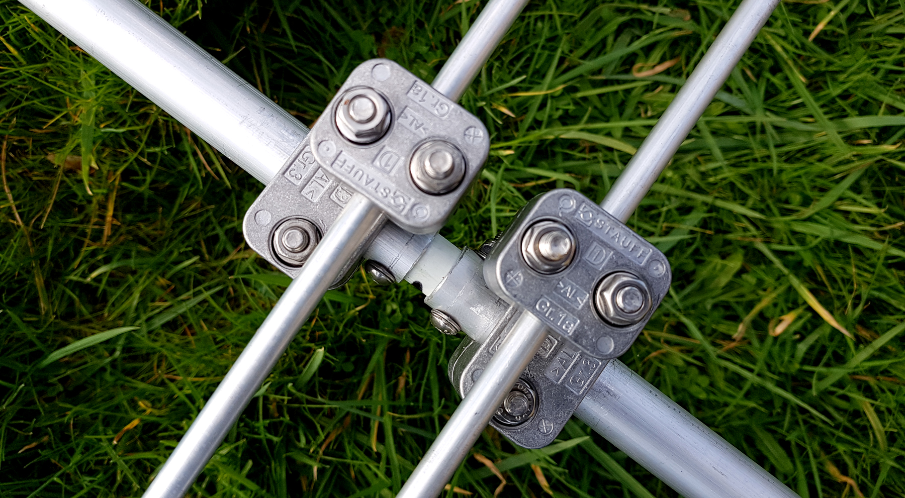
• Stauff Clamps [2 x 320AL and 2 x 10⁸A-AL] – Standard Aluminium Group 3 and Group 1A
• Allen Head Bolts M6 x 30 [x2]
• Allen Head Bolts M6 x 70 [x2]
• Allen Head Bolts M6 x 35 [x2]
SO239/N-Type Socket Mounting and 1:1 RF Choke Balun:
• Small cut-off of 1/8th inch aluminium angle
• M5 x 40 [x2] Button Head Bolts/Washers/Nuts
• M3 x 12 [x4] Button Head Bolts/Washers/Nuts
• 1 x N-Type PTFE Dielectric Bulkhead Socket [or PTFE SO239]
• Type 61 Snap-On Ferrite Cores over the coax at the feed-point (We found 6 worked well]
as each core provides around 215 Ohms choking impedance [Giving you well over 1.2kohms]
• A small length of good quality low-loss 50 ohm coax
Phasing Sections:
• Aluminium Tube: 5/16th x 16AWG or 8mm tube [an 80 cms section] from the spare you’ve already retained [2 of required]
• Stauff Clamps [4 x 320AL and 4 x 10⁸A-AL] – Standard Aluminium Group 3 and Group 1A
• Allen Head Bolts M6 x 35 [x2]
• Allen Head Bolts M6 x 70 [x4]
• Allen Head Bolts M6 x 40 [x4]
TIP!! – If you have access to one, use a ‘Pillar Drill’. This will really help get the brackets and radial supports correctly drilled and positioned.
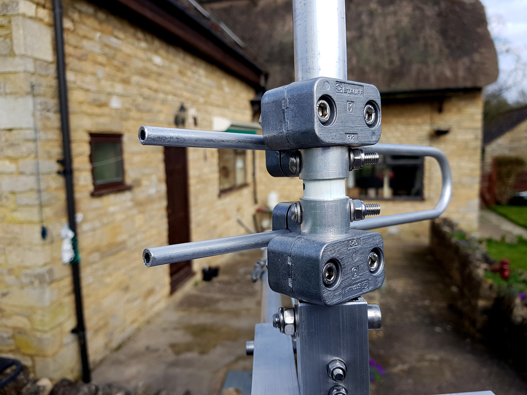
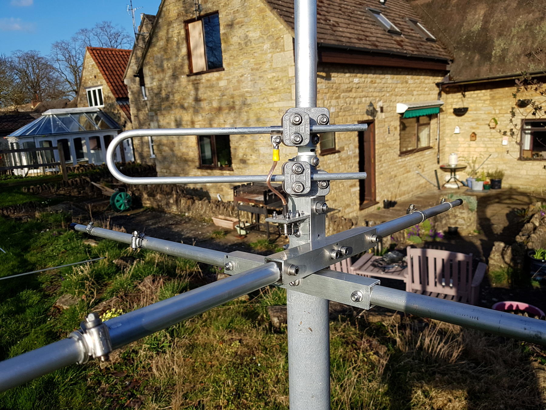
The ‘Hairpin Match’ is Tuned by Sliding the ‘Loop’ either ‘Inwards’ or ‘Outwards’ to Obtain the Best Match
I Found that a Distance of around 20cms from Clamp Centre was About Right
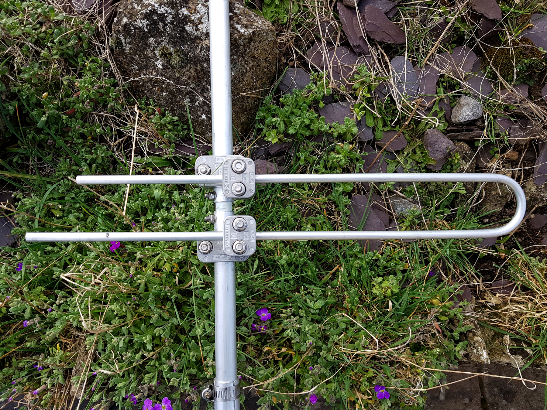
The ‘Total’ length of the Loop [measured from clamp centre to clamp centre] is 73 cms [32.5+32.5] plus 8cms for the 180 degree section. Any excess/overhang can be removed as this has no effect on the operation of the antenna
Vertical Radiator:
• Aluminium Tubing: 25mm diameter by 2mm wall [x 2.5m]
• Aluminium Tubing: 20mm diameter by 1.5mm wall from the spare you’ve already retained
• Aluminium Tubing: 16mm diameter by 1.5mm wall from the spare you’ve already retained
• Aluminium Tubing: 12mm diameter by 2mm wall from the spare you’ve already retained
Other Hardware Items:
• 20mm Solid Fibreglass Rod [1 x 50 cms] – for the base
• 16mm Solid Fibreglass Rod [2 x 50 cms] – for both phasing loops
• 50 M6 Stainless Nyloc Nuts
• 125 M6 Stainless Washers
• Assorted Stainless Worm Drive Clamps [Jubilee or Similar]
M6 Washers are used to ‘Bulk-Out’ the bolt holes so the nuts can fully tighten
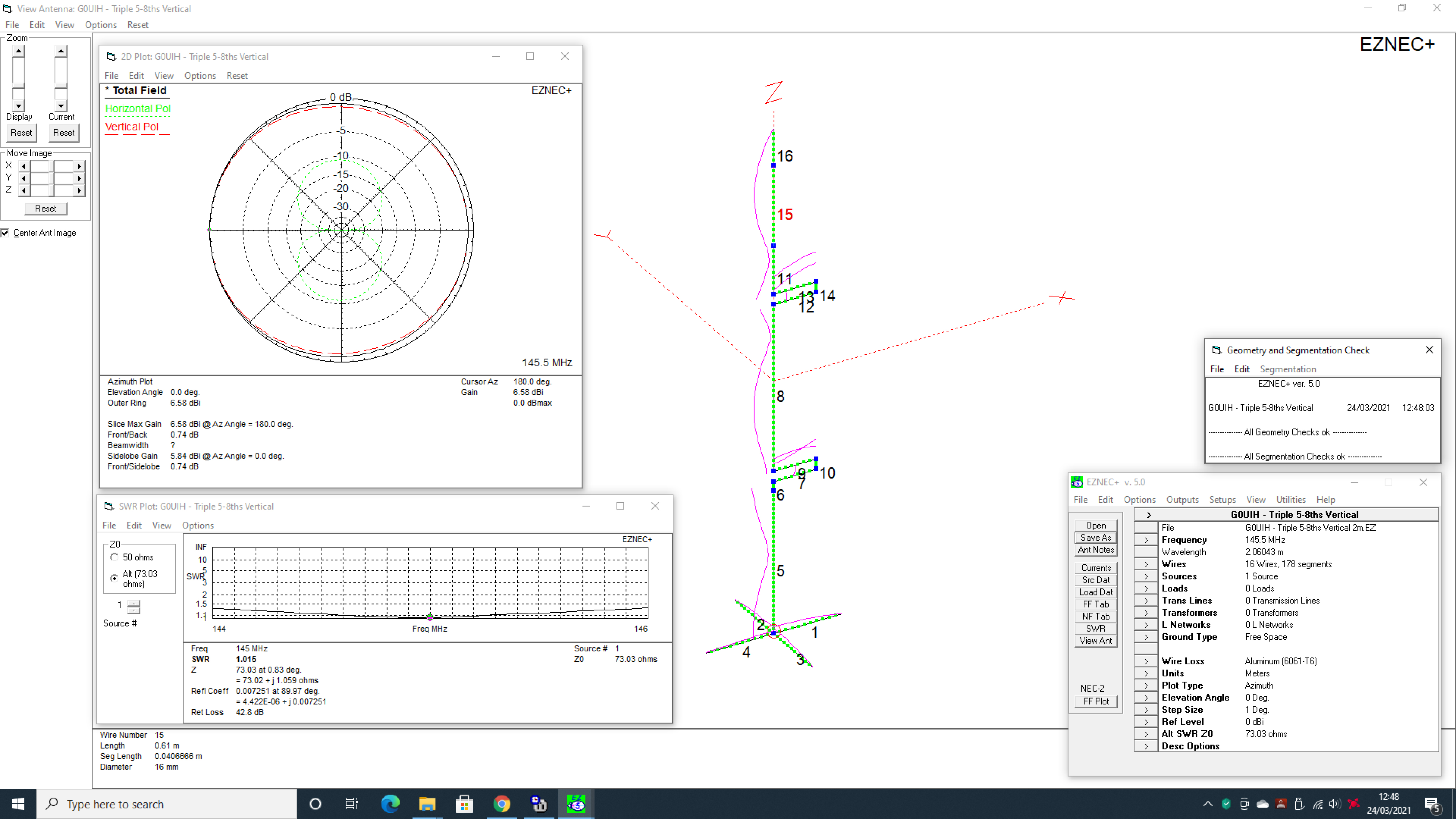
So, we move on to some modelling from EZNEC and the last images will give the constructor the full data and dimensions on how to achieve a working example. Click on each image to download a hi-res PDF of the model.
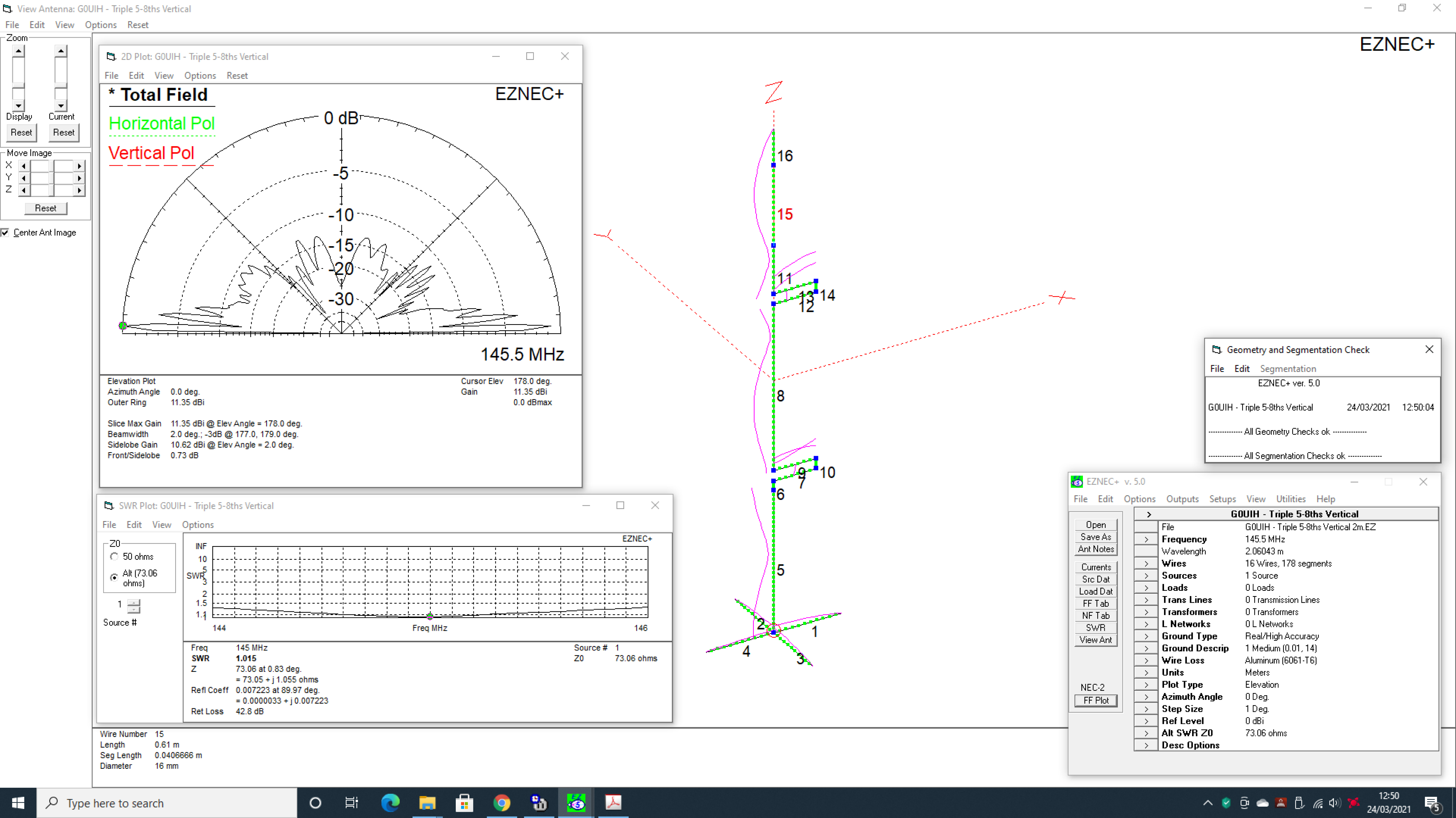
Including ‘Ground Gain’ – the Antenna is well over 11.3dbi. It should be a pretty potent affair!
Notice a Slight ‘Skew’ of Radiation Which is Positively Biased ‘OPPOSITE’ [180 degrees] to the Phasing Loops
Download the EZNEC File for this project here
Data On Wire Lengths
• Radials [Wires 1, 2, 3 and 4] = all 52 cms in length
• Main Radiator [Wire 5] 25mm diameter tube = 109 cms in length
• Main Radiator [Wire 6] 20mm diameter tube = 7 cms in length
• Main Radiator [Wire 8] 20mm diameter tube = 127 cms in length
• Main Radiator [Wire 11] 20mm diameter tube = 37 cms in length
• Main Radiator [Wire 15] 16mm diameter tube = 61 cms in length
• Main Radiator [Wire 16] 12mm diameter tube = 28.5 cms in length
Data On Phasing Loops
• Wires 7, 9, 12 and 13 are 5/16ths diameter tube = 32.5 cms in length
• Wires 10 and 14 are 5/16ths diameter tube = 8 cms in length
• As you can see from the images, I used a pipe bender. Each phasing loop is 73 cms in total measured from the centre of the aluminium clamp, around the loop and back to the centre of the other clamp. Any overhang can be ignored or removed.
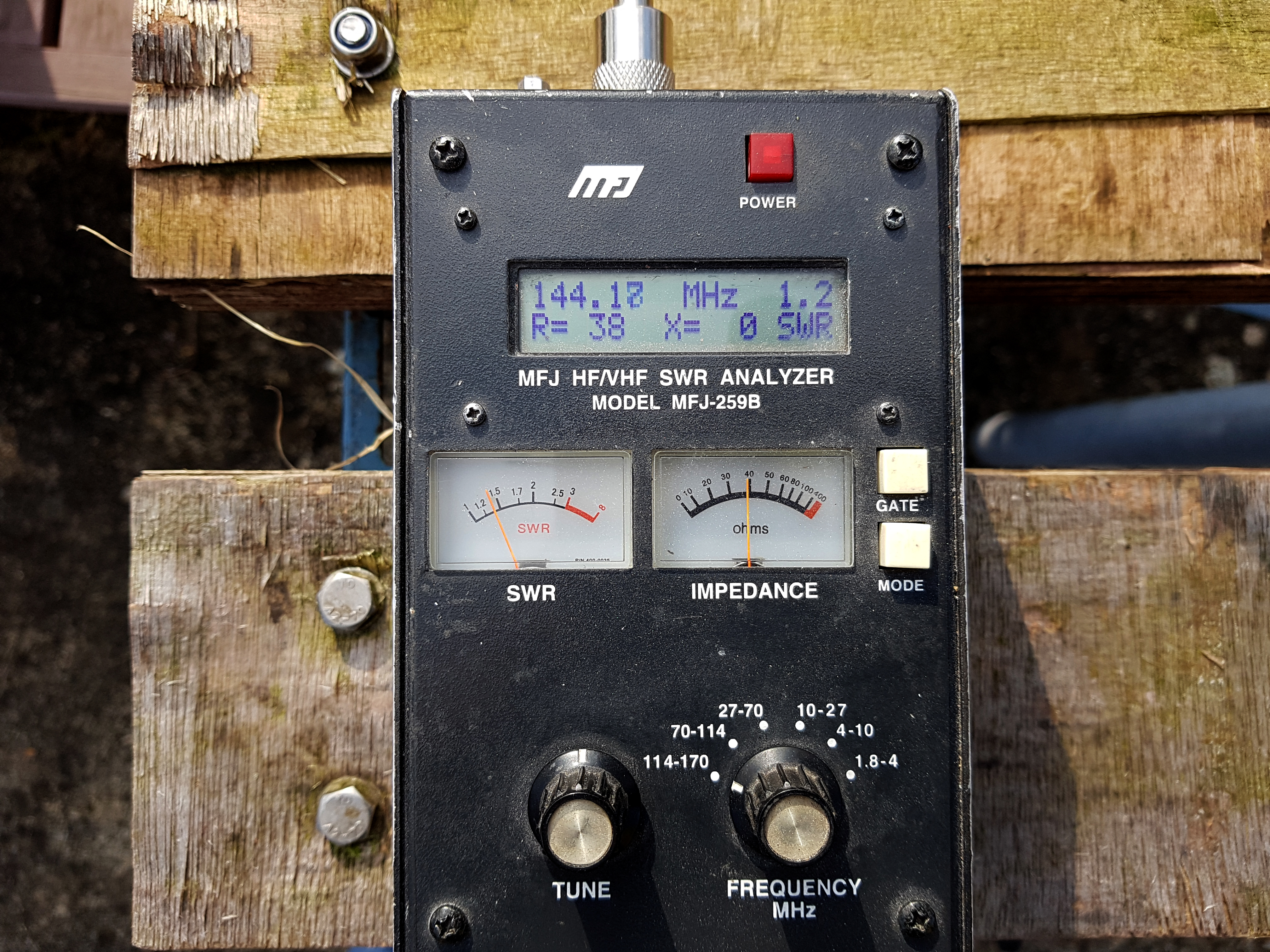
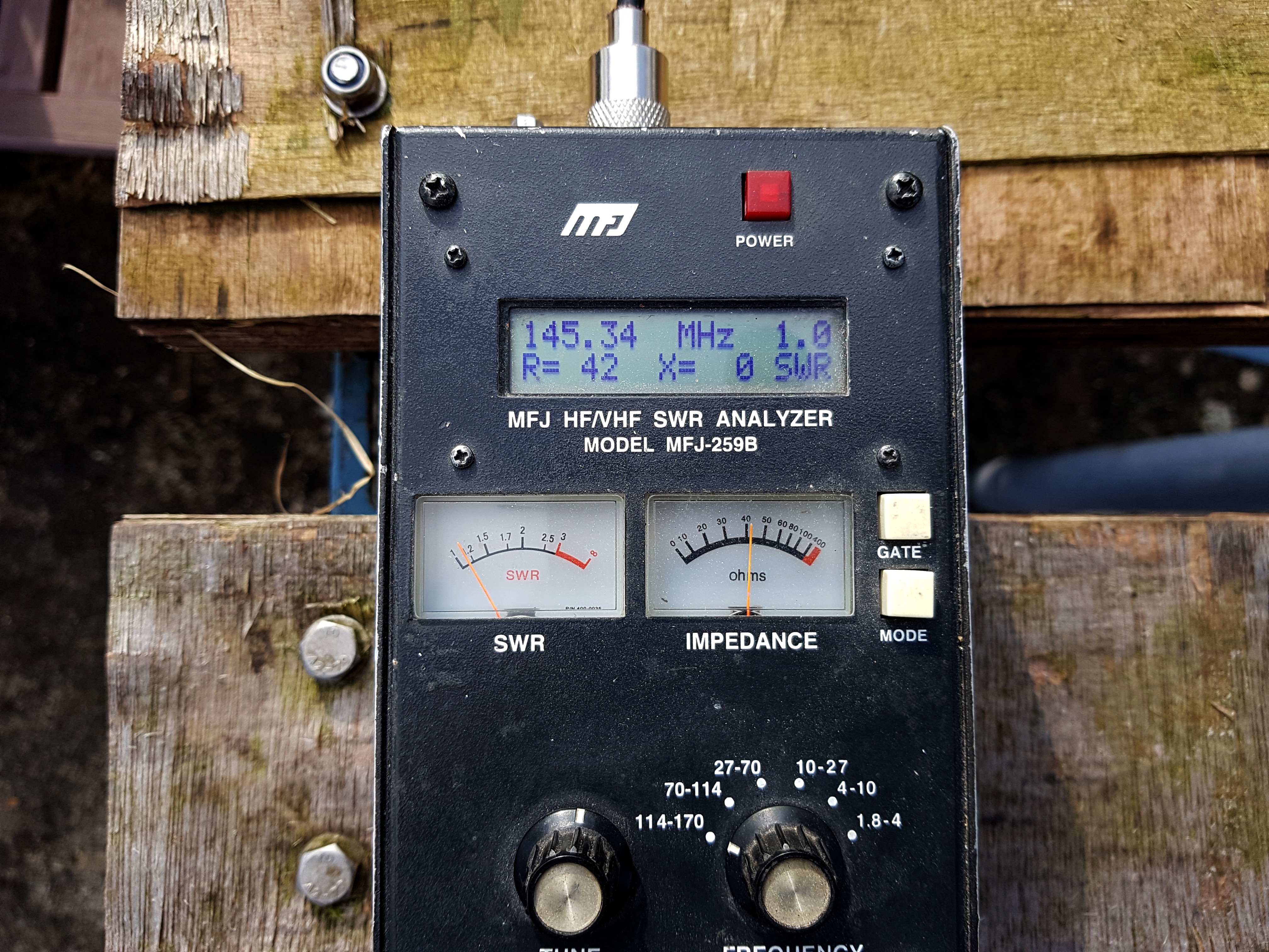
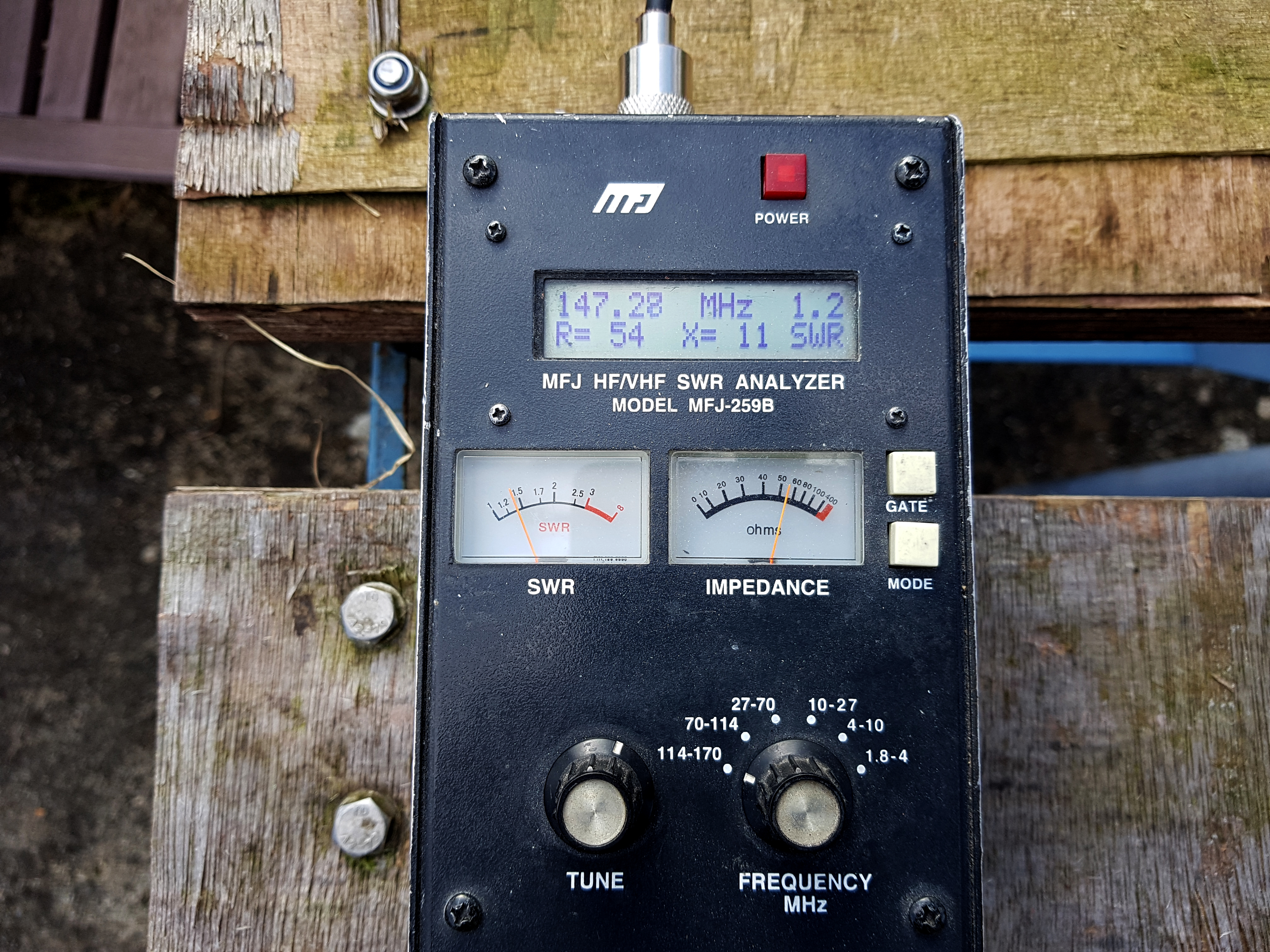
Here’s what you should see with respect to SWR and Bandwidth. The antenna looks to have a 2 to 1 bandwidth of over 9MHz. We found that between 144 and 147MHz, the SWR never went above 1.2 to 1.
If you do need to tune the antenna, then tune using the hairpin match. Antenna resonant too low? Move the resonant frequency up the band by reducing wires 16 and wire 6 by 1 cm at a time. To make the resonant frequency slightly lower, lengthen wires 16 and 6 by 1 cm. We found a ‘1 cm shift’ on both these tubes, moved resonance by around 400Khz.
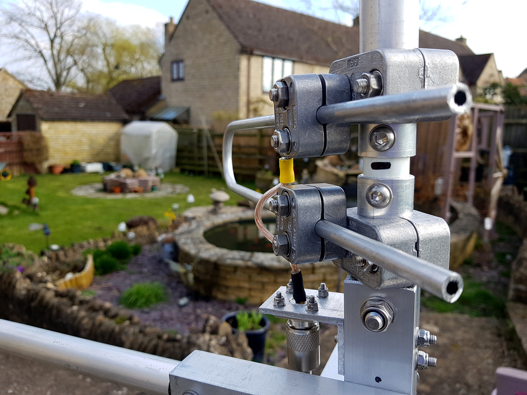
Homebrew 1:1 RF Choke Balun
After initially setting up the antenna, I found that if I put my hand on the coax near the feed point or moved the coax around somewhat, then I’d get minor changes in the SWR. Nothing much, but it did indicate a small amount of common-mode currents on the braid of the feeder. This was easily ‘Quietened Down’ by using 4 x Type 61 ‘Snap-On‘ cores which I purchased from RS Components.
These cores were clamped over a small section of 10mm diameter ‘Formula-Zero‘ low-loss 50 ohm coax. At the same time, I decided that it was best to NOT tape the coax/balun directly to the square section mounting at the base, but keeping the feeder away from any metallic object by a few inches. This additionally removed any chance of RF coupling between the coax and the support pole. These 2 additions certainly helped here.
Conclusion: This is a great antenna to build. It may take a while and the parts will be well into three figures, but you won’t be replacing any of it in the years to come. Only the normal TLC that most antennas need.
Plus Points Compared With ‘White-Sticks’
• Handles QRO [Easily 1kw+] – no burnt out ceramic disc capacitors
• Fully tuneable/adjustable tube lengths and hairpin matching
• Radials are sturdy aluminium tubes. No stainless rods threaded into soft aluminium
• Much better bandwidth. Using tubes [rather than wire] increases the bandwidth considerably
• No lossy coils. Most ‘White-Sticks’ have a coil/matching system with a capacitor
• Should withstand 100mph winds
• Minimal maintenance
Good luck with your project.
If you build this antenna – let us know how you got on and what you think.
73 – Steve G0UIH/VK2IAY Q82.uk

