
Constructing Your Own Gamma Match
There’s plenty of online info regarding the ‘Gamma Match’, some of it quite technical. Various calculators, in my experience give quite different results depending on which one you use. I’ve tried many of them and the results in many just didn’t seem to add up to the software predictions. So – which one is right. My answer here is the ‘one that actually works for you’ – regardless of what any ‘calculator’ says.
We’re not going into the technical ins-and-outs but will give pointers on how to construct a unit that will do the job for you.
I’d say as an initial pointer, if you are constructing a Yagi antenna, in particular a low impedance version that has a natural impedance [Z] of around 20-40 ohms then go the ‘Hairpin Match’ route.
Hairpins are a very straight forward affair and generally hassle free. We have some info here on the ‘Hairpin Match’ and show you just how easy it is to construct and how you can get them to work.
If you are the builder of a Delta Loop antenna, then we suggest a gamma match as the preferred method. Gammas have been touted online as an ‘Up‘ impedance transformer, but this is not totally accurate. Yes – we’ve all seen gamma matches on Yagis which normally have an impedance lower than 50 ohms, but take a ‘Delta Loop’ for instance.
A single Delta Loop [or quad loop] has a natural impedance of around 90-100 ohms although the exact value drifts either side of resonance. We’ve always matched our single loops with a gamma match. Likewise, many of the ‘Vortex‘ multi-element delta loops are naturally a higher impedance than 50 ohms. All were matched very successfully using a gamma match. So, the gamma is a useful impedance matching device from the both the ‘low’ and ‘high’ end.
The small ‘Technical’ Bit – The Gamma Match is a series capacitor, but that’s just part of the story. The rod which runs parallel to the driven element can be thought as a parallel shorted transmission line stub, adding shunt inductance. The added series capacitance is used to null any resulting inductive reactance.
In short, a gamma match has two adjustments; the position of the shorting bar on the driven element (which varies the impedance), and the variable capacitor (tube/PTFE and rod) in series with the inductance of the bar (which tunes out any reactance).
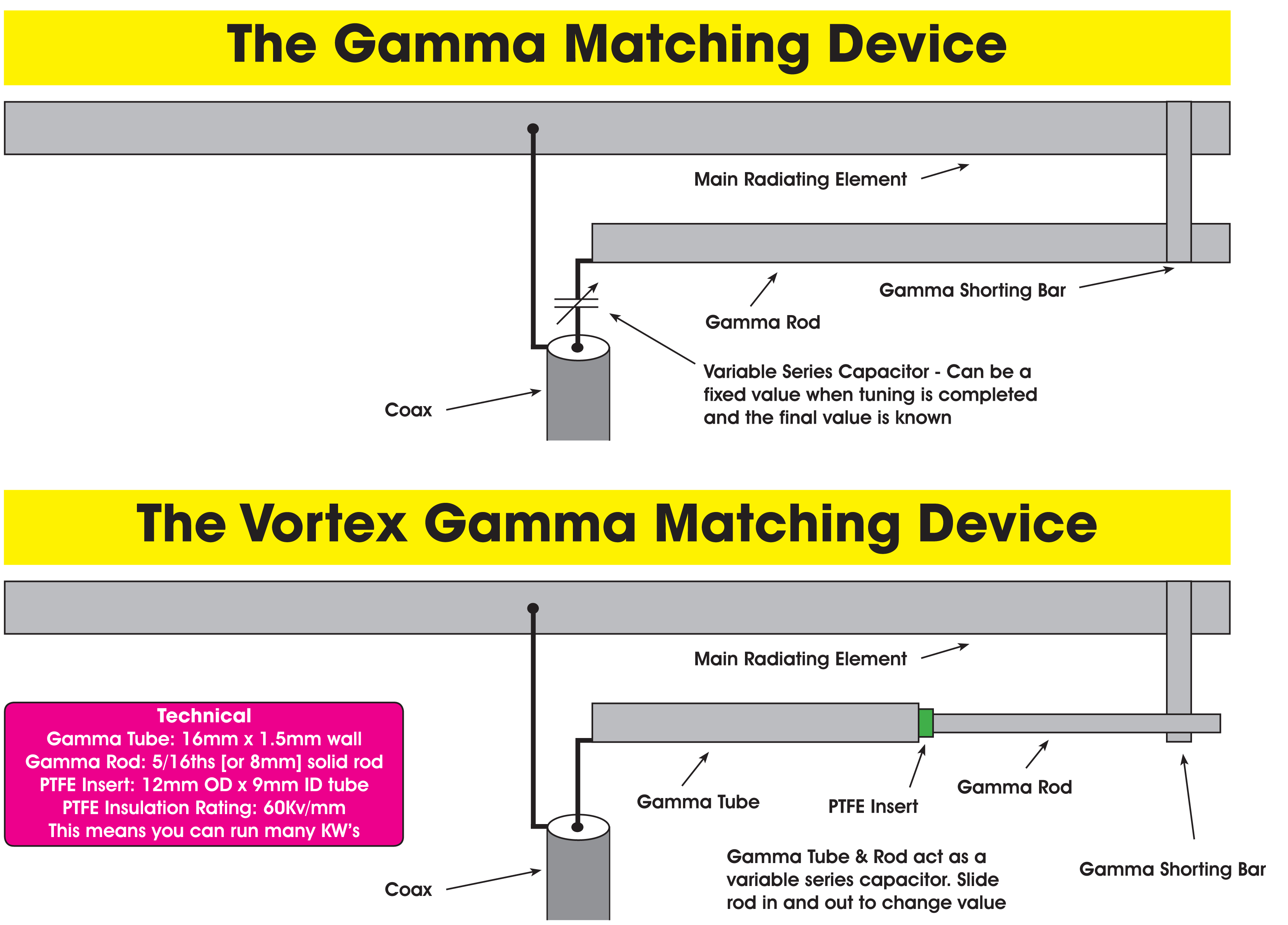
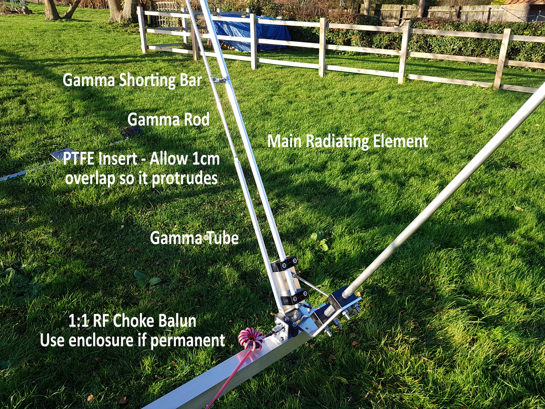
The above illustration shows a normal gamma match and below is the version I created for all Vortex builds. The use of PTFE as an insert was key in that it has superb insulation characterises [60kv/mm] which means you can run kilowatts of power with any arching between the gamma tube and rod.
In a commercial antenna, we had an antenna running at 20kw [key-down] using a 16mm tube and rod in the same configuration as shown.
Below is a typical setup using an SO239 with PTFE insulation. The SO239 feeds to an M8 bolt which then feeds to the gamma tube which has a PTFE insulated section inserted into its full length. The M8 bolt is surrounded by a small PTFE insert which prevents the nylon block melting under high RF power. Thus the gamma tube is supported by the nylon mount. The M8 bolt provides the mounting for the gamma tube which is 16mm aluminium tube, flattened at the end and an M8 hole drilled.
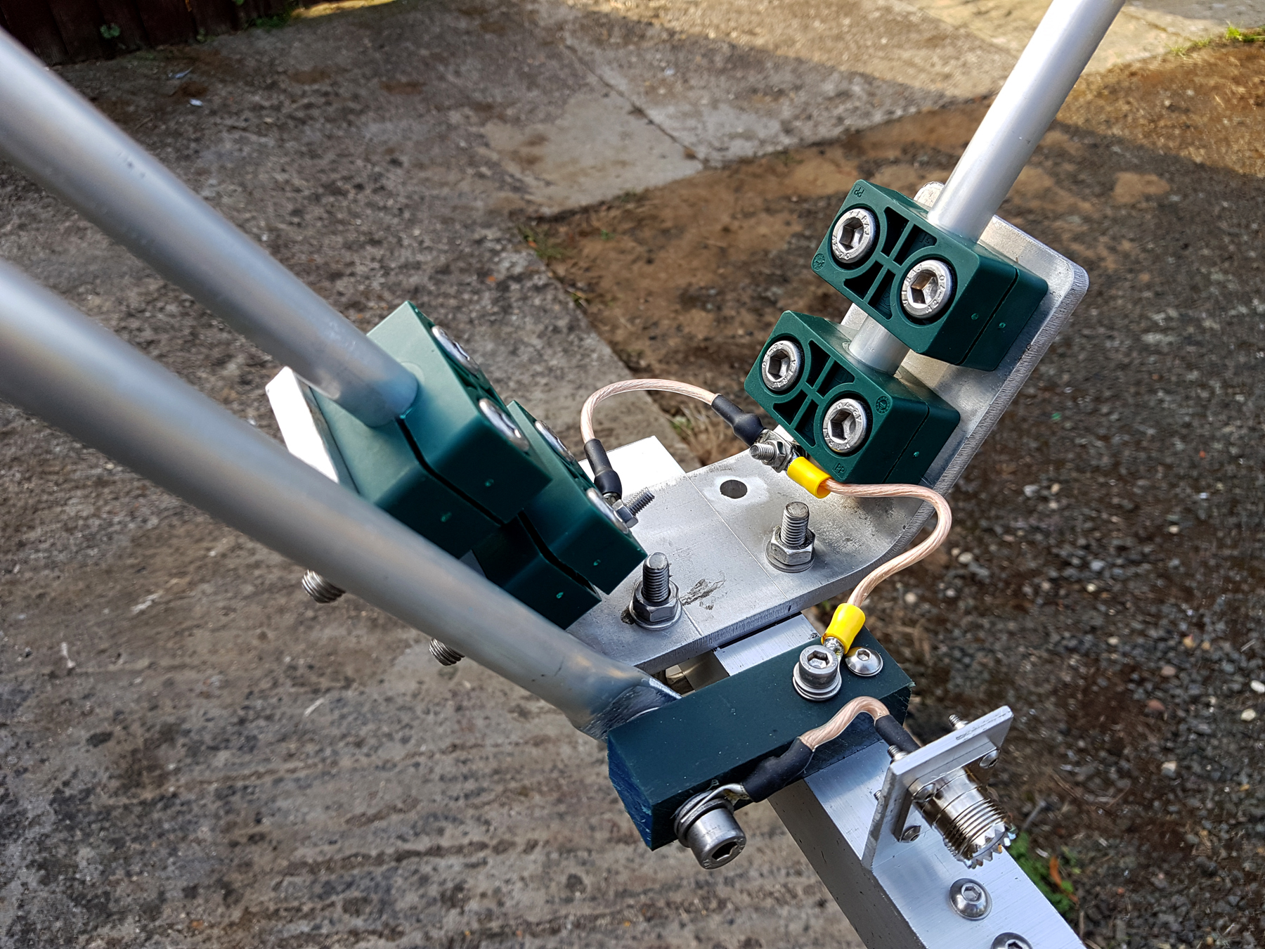
The earth link can be seen with the yellow ring terminal connector. The M6 bolt through this ring, connects to the boom which obviously has continuity with the chassis/braid/earth of the SO239 angle bracket. This then finally connects to the centre of the driven element loop. And of course – don’t forget the loop ‘link’ wire on the far side!
So – you fancy a ‘Gamma Match’ – here’s a rundown on gamma tube lengths, rod length and where to position the shorting bar [all measurements are in cms]. All the below data is from ‘live’ builds between 2008 and 2020 – all 2 element versions. Single element antennas, together with 3/4/5/6/7 etc element versions will also differ but the table makes a good starting point. You should refer to the ‘Tuning a Gamma Match – If You Have No Data‘ section [further down this page] to aid your setup.
Typical data presumes you are using a 16mm x 1.5mm wall tube and an 5/16ths [8mm] rod. PTFE is 12mm outer diameter and 9mm inner. In theory, the 1.5mm wall of the PTFE should have an insulation of around 90Kv and will handle many Kw.
IMPORTANT NOTE: Don’t use nylon instead of PTFE for the insert. It’s cheaper, yes, but poor economy for sure. The insulating properties are not that good but it should be ok for 200w or so. We tried it in the early days and 1kw could cause a big flashover, melting the nylon and may also damage your radio equipment.
Get your 12mm OD by 9mm ID PTFE here. Our source in Asia has been very reliable for the last 5 years at a price of only 35% of equivalent UK stock. The quality is also top-notch!
| Band | Tube Length | Rod Length | Shorting Bar Position [cms above tube] | Gamma Rod Inside Tube [cms] |
| 10 | 50 | 150 | 91 | 20 |
| 11 | 50 | 100 | 24 | 23 |
| 12 | 55 | 100 | 26 | 27 |
| 15 | 65 | 100 | 26 | 34 |
| 17 | 80 | 120 | 72 | 30 |
| 20 | 80 | 165 | 111 | 37 |
Tuning a Gamma Match – If You Have No Data.
The easiest way is as follows. You should only require a good SWR meter, although an antenna analyser is preferable. Try it a few times. After a while you won’t need a data sheet and you’ll be able to do it nearly with your eyes closed [well not quite!].
Remember the rod length and position changes the ‘Capacitance‘ and bar removes the ‘Reactance‘ (X). There’s no ‘Right’ or ‘Wrong’ – it’s where you get your best match.
- Set both rod and bar fully inwards [the SWR will be high]
- Pull the rod out 2-3 cms and move the bar upwards by 5 cms – the SWR should slightly improve
- Pull the rod out 2-3 cms more. You may find the reactance ‘X’ high. Move the bar up another 5 cms and the ‘X’ will drop – improving the SWR
- Move the bar a few more cms higher – the SWR should continue to drop
- Move the rod out until the SWR stops dropping or begins to rise. Move the bar upwards about 5-10 cms more. The SWR will continue to drop.
- Continue with this method. When you get close – push the bar up another 5 cms it should flatten out nicely around 1.0:1
Notes to Readers: The data and information shown in this article is based on our own experiences and is purely for reference and no guarantees are given. Your actual build may have totally different settings to that shown in the table for many reasons. Also our feed-point location is not the same now as it was 5 years ago [although it’s close] so that ‘WILL’ affect things. Unfortunately, we can’t assist with technical queries on builds that won’t ‘play-ball’ as such or where matching proves difficult.

