Build a High Performance 6m 3 Element Yagi
I’ve just finished reading my most recent copy of ‘Radcom’. I enjoy reading over all for the technical information and data that relates to the antenna projects each month.
So, this month’s [March 2021] antenna project by Mike Parkin G0JMI is a ‘homebrew’ build of a 3 element 6m Yagi. It’s a good straight forward design and looks to have a natural impedance of around 40-50 ohms as no matching device is included which sounds ok, but lower impedance Yagis of around 30-35 ohms offer better performance and are easily matched with a hairpin.
It’s no secret that there’s quite a variety of ways to design a 3 element Yagi and with antennas there’s normally more than one way to crack a ‘nut’ as they say. You can have equal spacing between reflector and driver and equal spacing between driver and director. It’s a kind of ‘Middle of the Road‘ no thrills scenario – but makes a good starting point.
Equally, you can revise the driver to director spacing by pushing the driver forward to give a wider bandwidth or by doing the reverse to give higher gain. However, one item in the article spurned me into modelling the design. That reason being is that the quoted front-to-back ratio is only 15db. That’s really poor in anyone’s book for a 3 element Yagi.
So, out came EZNEC+ and I modelled the design exactly per the article because something ‘looked’ wrong. I’ve never seen such a low front-to-back in this type of design unless the measurements are incorrect.
It seems that there’s a typo in the editorial as my EZNEC+ calculations gave a nice antenna with 7.33dbi forward gain and 25db front-to-back. Very acceptable in anyone’s book.
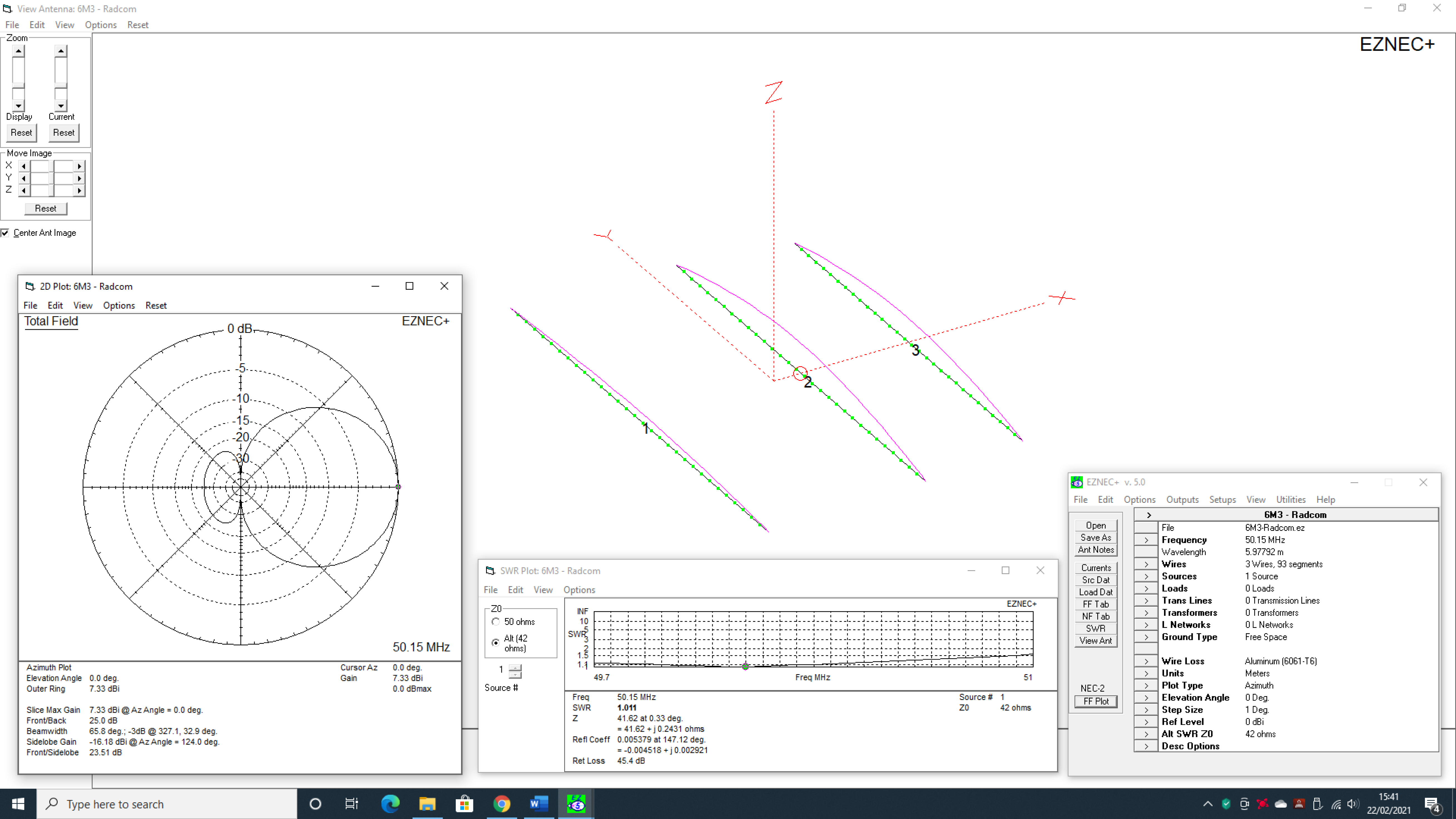
The design shows 7.33dbi forward gain and 25db front to back. No issues here.
The ‘Radcom‘ article gives the user all construction details when using 12mm tube. Personally, I think the use of single section 12mm tubes gives a rather flimsy end product. My personal suggestion is to use a 5/8ths inch [15.875mm] tubes to form the centre part of the elements. This creates a much more sturdy affair without adding too much extra weight.
So, without changing much in the design – I’ve created an identical version below – but modelled using 5/8ths diameter [15.875mm] tubes for the centre part of the elements. The modelling result required slight changes in tube lengths but not by much.
The model also wasn’t put through any lengthy optimisation processes but my hastily created design ended up with a 36.7 ohm simulation. This gave a slightly higher gain at 7.44dbi than the ‘Radcom’ variant and a very healthy front-to-back boost by over 6db to 31.16db and higher return loss. You could easily match this design with a ‘Hairpin’ Match [Shunt] at the feed-point which we’ve done successfully with many low impedance designs in the past.
Modellers and experimenters could potentially get the gain to over 8dbi with around 25db front to back ratio but at the expense of some bandwidth.
As with many Yagi designs, we’d encourage the use of a good quality 1:1 RF Choke Balun at the feed-point.
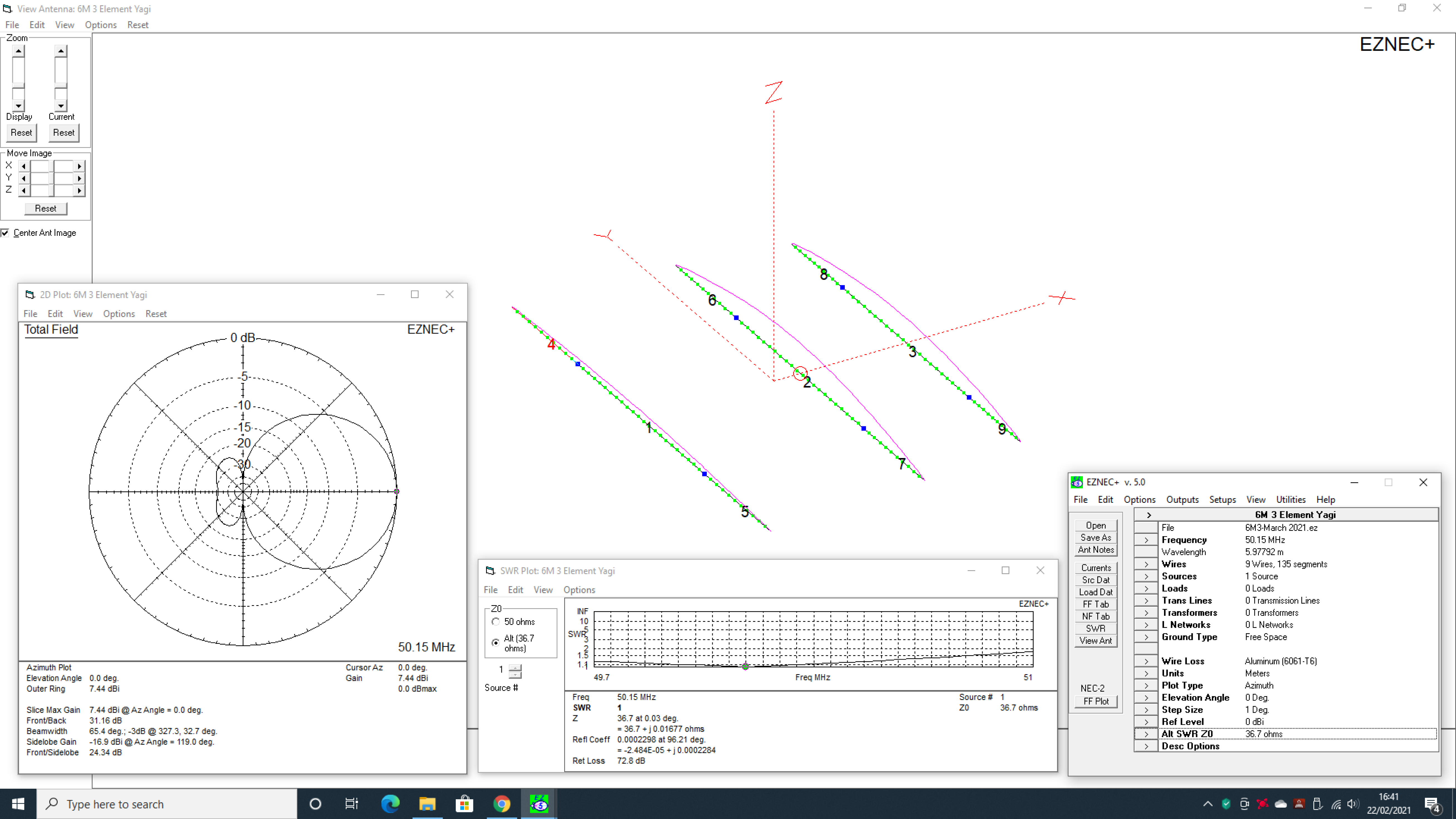
This makes the array much stronger and less flimsy without adding too much extra weight
The array also has slightly increased gain [7.44dbi], over 6db better front-to back ratio and higher return loss
Of course, for those ‘in the know‘, we are all using computer programs that run the NEC-2 calculating engine. As mentioned before in some of my other articles on the site, the accuracy of NEC-2 engine can’t be compared to the much more expensive NEC-4 engine that’s used in EZNEC Pro/4. That’s not to say EZNEC+ is not useable – it’s just not quite as accurate.
In practice, I found EZNEC+ gave excellent results provided you took the slight frequency upwards ‘bump‘ into account. In most cases I found that everything was resonant just a tiny bit high, so in ‘real-world’ builds – this was taken into account.
BUILD DATA – G0UIH – 3 ELEMENT 6m YAGI [Click on the image above to view PDF]
Reflector:
Wire 1: 5/8ths x 16 Gauge [1.626mm] wall tubing. Length = 1.50m [150cm]
Wire 4: 12mm x 2mm wall tubing. Length = 78.5cm
Wire 5: 12mm x 2mm wall tubing. Length = 78.5cm
Driven Element:
Wire 2: 5/8ths x 16 Gauge [1.626mm] wall tubing. Length = 1.50m [150cm]
Wire 6: 12mm x 2mm wall tubing. Length = 72.1cm
Wire 7: 12mm x 2mm wall tubing. Length = 72.1cm
Director:
Wire 3: 5/8ths x 16 Gauge [1.626mm] wall tubing. Length = 1.50m [150cm]
Wire 8: 12mm x 2mm wall tubing. Length = 60.2cm
Wire 9: 12mm x 2mm wall tubing. Length = 60.2cm
Spacings:
Reflector to Driver [Element centre to centre] = 1.08m [108cms]
Driver to Director [Element centre to centre] = 0.72m [72cms]
Both sizes of aluminium tubes are currently available at ‘Aluminium Warehouse‘ in Herts.
Ideas for building the ‘Hairpin Match‘ can be found here. I’ve built a few of these and found that a spacing of around 17cms was pretty good and set the hairpin shorting bar at 15.5cms.
Try it out – you won’t be far away.
As they used to say on ‘Blue Peter‘ – ‘Here’s one we made earlier’…..
