
A Dual Band High Performance Delta Loop for 10 and 15m
Now that sunspot cycle 25 is getting into action, here’s a premier Delta Loop project for two of the higher HF bands. With 3 elements on 15m and 4 on 10m, this is a powerful dual-bander with enough clout to bust most pile-ups and quite easily.
In this article, rather than show you a built antenna system, I’ll run through some of the ways I’ve used to get loop antennas working well, without relying on the wire lengths in the EZNEC models which in practice are not accurate and don’t work well in real-world builds.

The ‘building’ part is really down to each individual, as here, we’ll concentrate more on getting it right electrically rather than mechanically but we’ve given some basic ideas on the boom.
Before going further, I suggest you read this article https://q82.uk/deltataper which runs through the background and what we do to get around some of the problems.
Click on any of the images in the article to show a higher-resolution PDF which may help in your analysis.
With this in mind, I’ll go through the steps as if I was building this myself from scratch.
Boom:
This antenna employs a boom length of around 7.5 meters. With this in mind, my thoughts would be to use a centre section of say 50mm x 50mm box section with 4mm wall and 40mm x 40mm x 2mm wall outers.
The centre section would be a complete 5m uncut section with the smaller 40mm box being slotted in at each end. The 40mm box would not need to handle more than 2 elements with the 15m and 10m reflector at one end and a 10m director at the other. All other elements would be mounted on the sturdier 50mm box section.
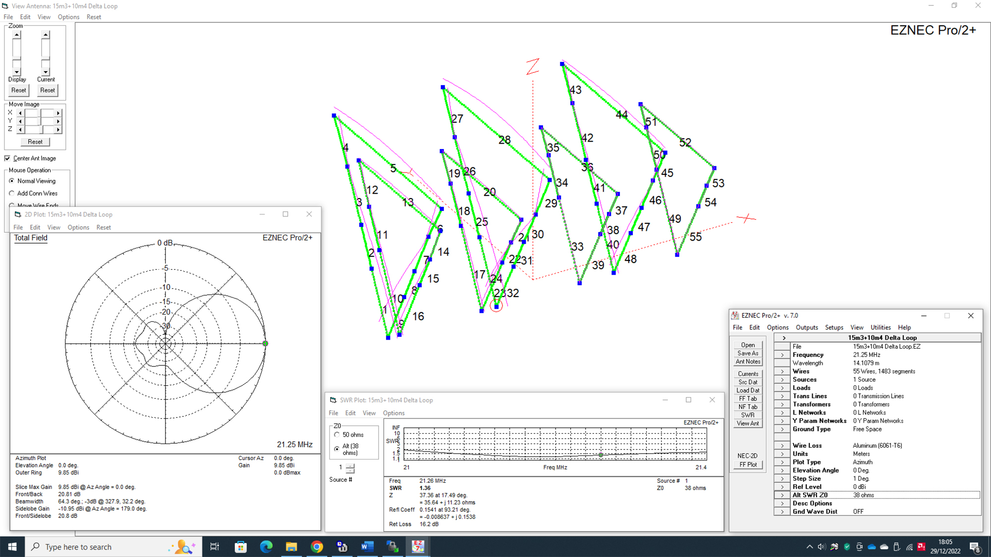
EZNEC Model – Element Position
Examine the EZNEC model file [downloadable below] and use the element spacing as per the model. Here we don’t need to change anything. With this in mind, we have the following data.
Distance from Boom end in meters.
15M Reflector: 0
10M Reflector: 0.295
10M Driver: 2.395
15M Driver: 2.77
10M Director D1: 4.895
15M Director D1: 5.77
10M Director D2: 7.395
EZNEC Model – Element Tuning
Examine the EZNEC model and make a copy of the original file just in case you overwrite it.
Ignore the EZNEC wire lengths and build your loop with whatever materials you have. There’s no right or wrong way here, only that each loop is built accurately based on the maximum dip as shown on your analyser. See the frequencies that you are aiming for below.
Tune each loop individually at about 5 feet above ground on a small test pole/post.
Remove each tested loop ‘out of the way’ when you go on to test other loops so it doesn’t affect or interact with the next.
15m Reflector Resonance Model:
Delete wires 10-55 so you just have the 15m reflector loop.
Reconnect the source to the base of Wire 1
Run an SWR curve between 21.600MHz and 22.220MHz as below [just for your reference]
Do not save the original file although you can do a ‘Save As’ to retain the element plot
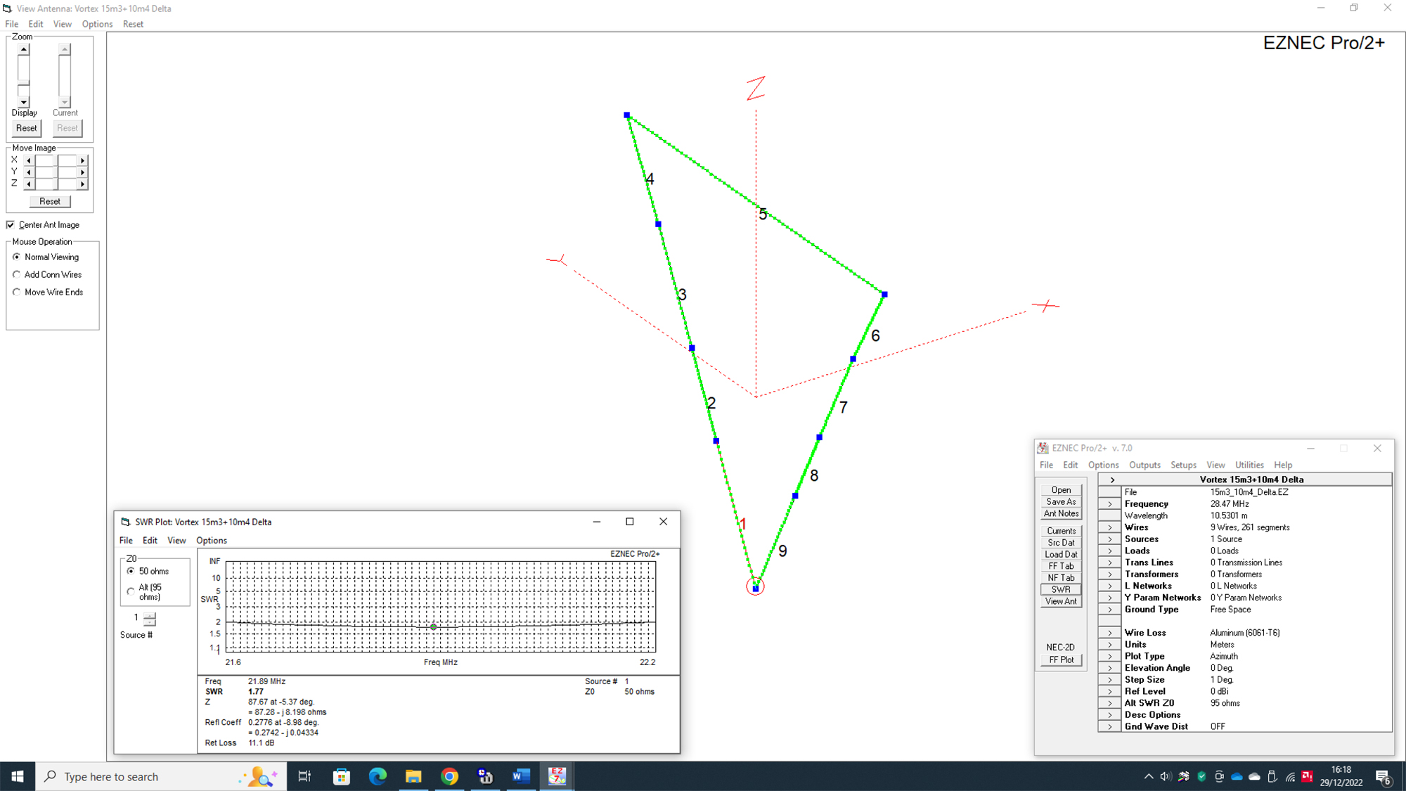
Real Life Building:
Connect your antenna analyser at the source and tune the loop for the lowest dip at 21.890Mhz
10m Reflector Resonance Model:
Delete all wires apart from the 10m reflector loop.
Reconnect the source to the base of Wire 1
Run an SWR curve between 27.600MHz and 28.400MHz as below [just for your reference]
Do not save the original file although you can do a ‘Save As’ to retain the element plot
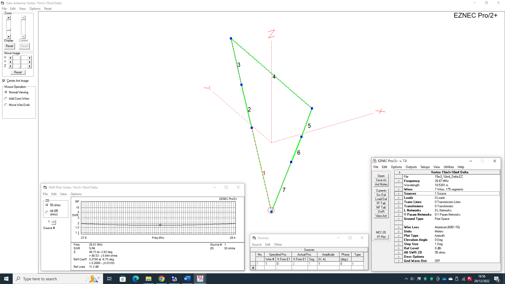
Real Life Building:
Connect your antenna analyser at the source and tune the loop for the lowest dip at 28.010Mhz
10m Driver Resonance Model:
Delete all wires apart from the 10m driven element loop.
The source is already connected to the base of Wire 1
Run an SWR curve between 29.700MHz and 30.300MHz as below [just for your reference]
Do not save the original file although you can do a ‘Save As’ to retain the element plot
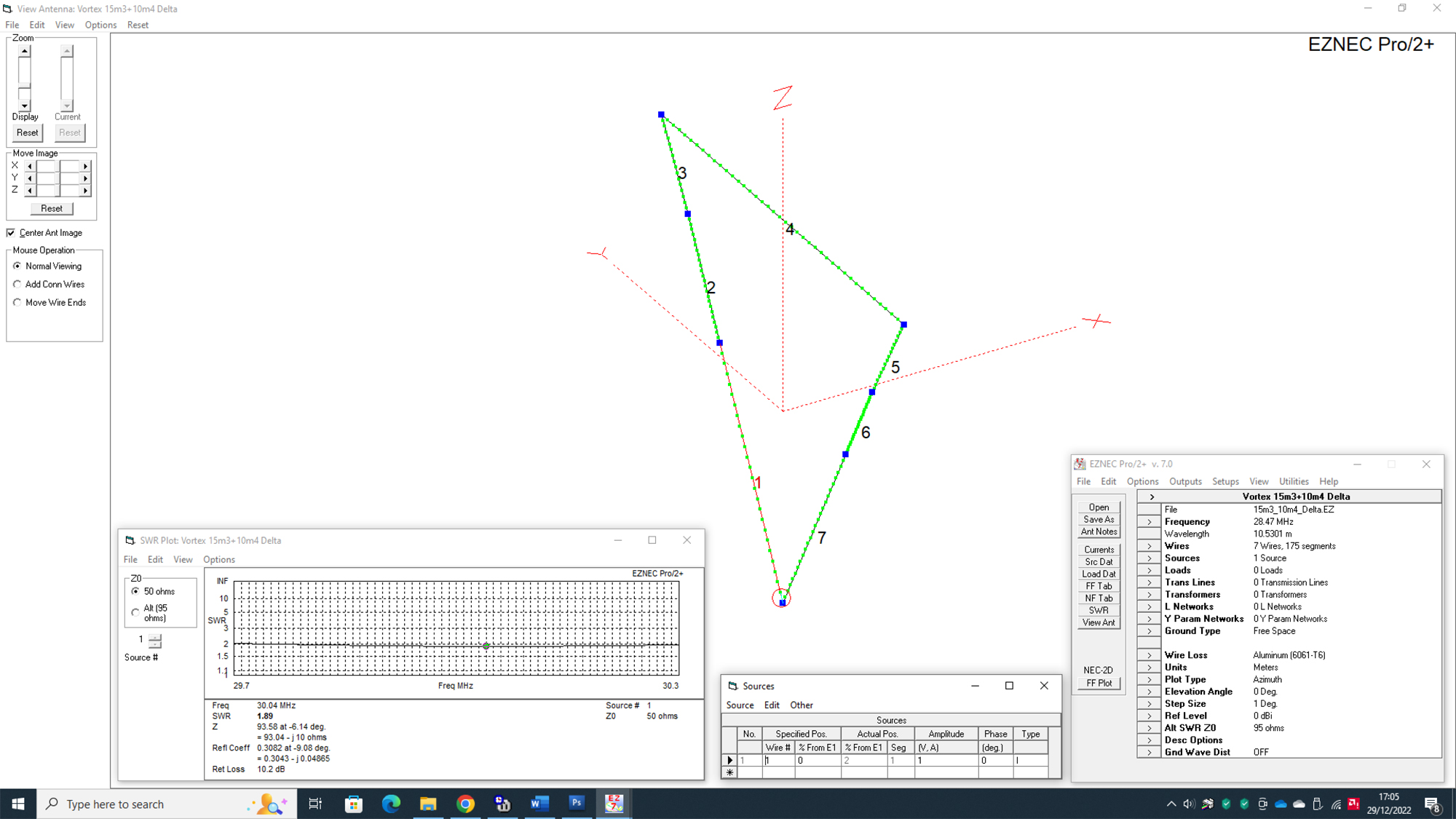
Real Life Building:
Connect your antenna analyser at the source and tune the loop for the lowest dip at 30.040Mhz
15m Driver Resonance Model:
Delete all wires apart from the 15m driven element loop.
Connect the source to the base of Wire 1
Run an SWR curve between 21.750MHz and 22.260MHz as below [just for your reference]
Do not save the original file although you can do a ‘Save As’ to retain the element plot

Real Life Building:
Connect your antenna analyser at the source and tune the loop for the lowest dip at 22.000Mhz
10m Director D1 Resonance Model:
Delete all wires apart from the 10m Director D1 loop.
Connect the source to the base of Wire 1
Run an SWR curve between 30.750MHz and 31.270MHz as below [just for your reference]
Do not save the original file although you can do a ‘Save As’ to retain the element plot
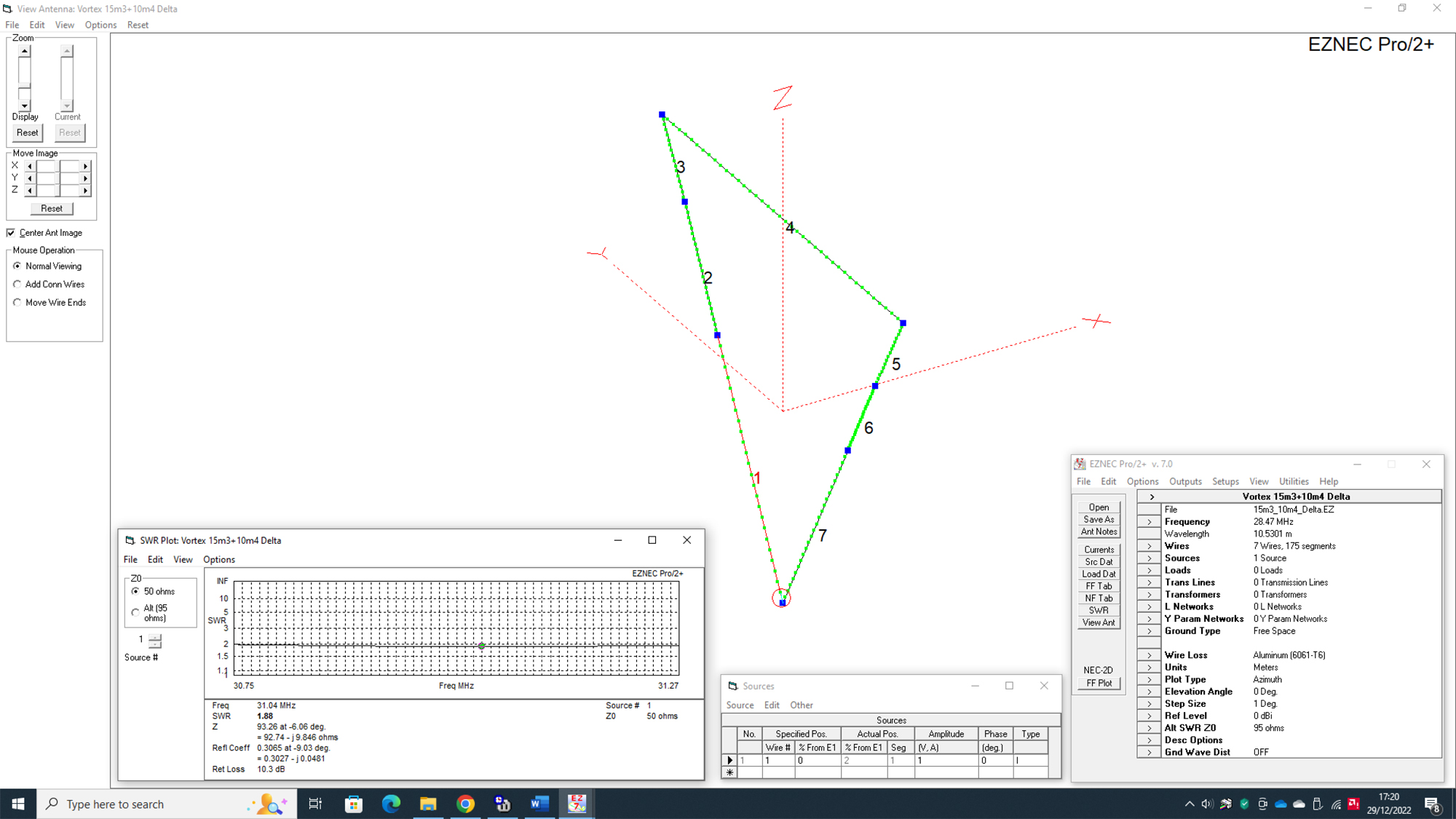
Real Life Building:
Connect your antenna analyser at the source and tune the loop for the lowest dip at 31.040Mhz
15m Director D1 Resonance Model:
Delete all wires apart from the 15m Director D1 loop.
Connect the source to the base of Wire 1
Run an SWR curve between 22.850MHz and 23.270MHz as below [just for your reference]
Do not save the original file although you can do a ‘Save As’ to retain the element plot
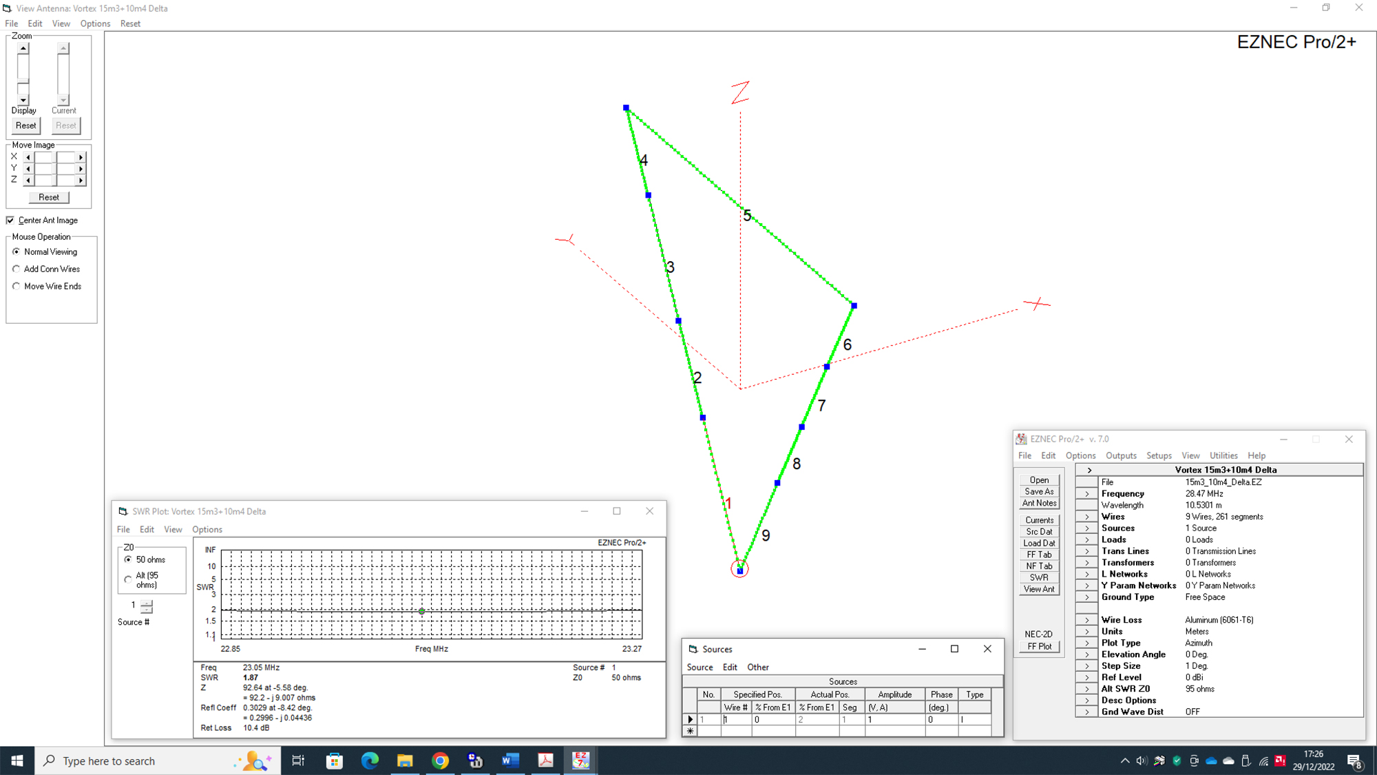
Real Life Building:
Connect your antenna analyser at the source and tune the loop for the lowest dip at 23.050Mhz
10m Director D2 Resonance Model:
Delete all wires from 1 to 48.
Connect the source to the base of Wire 1
Run an SWR curve between 32.110MHz and 32.34MHz as below [just for your reference]
Do not save the original file although you can do a ‘Save As’ to retain the element plot
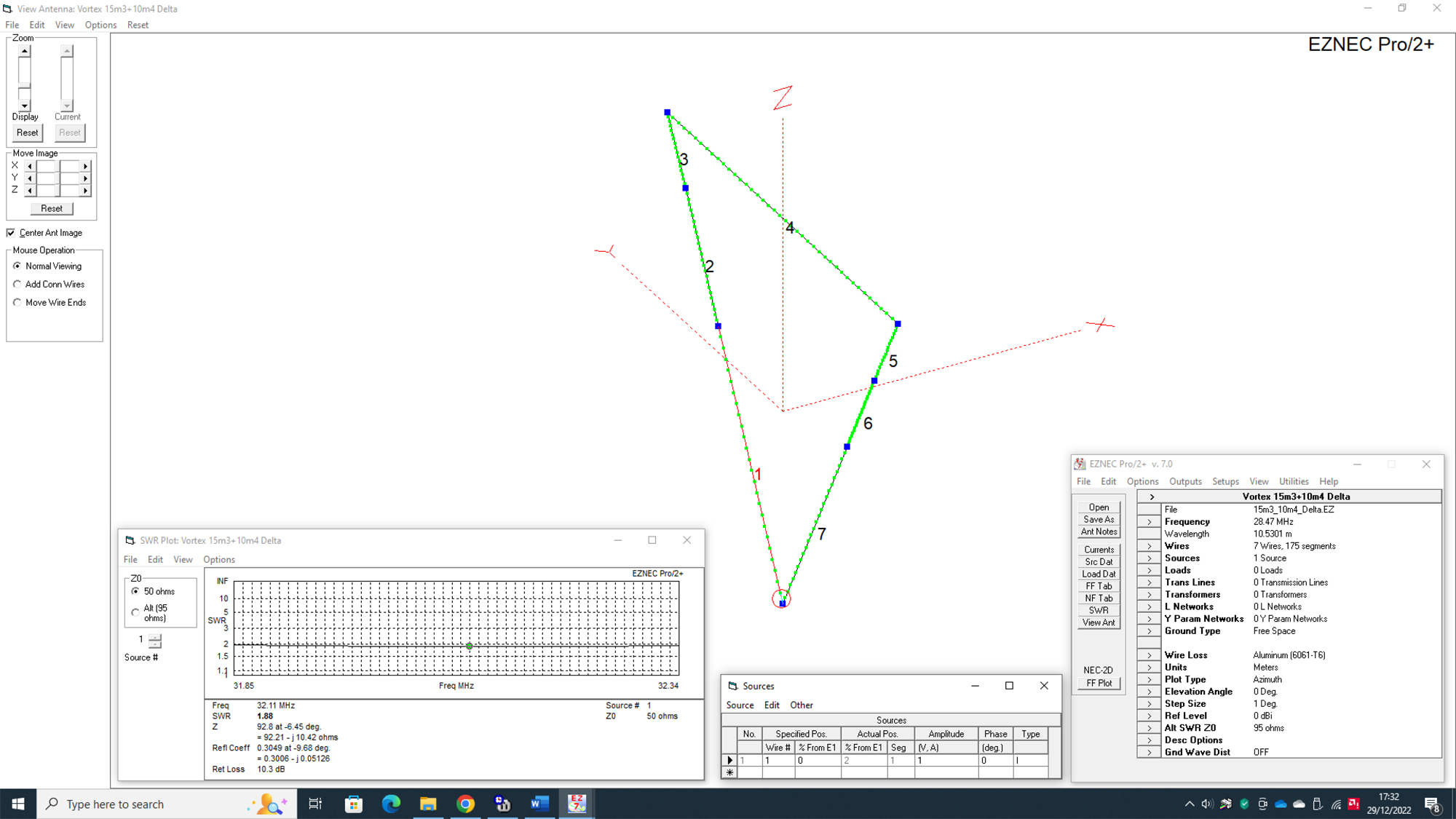
Real Life Building:
Connect your antenna analyser at the source and tune the loop for the lowest dip at 32.110Mhz
Final Physical Build:
Recombine all the now pre-tuned elements back into the array.
Connect an antenna analyser at the feed point. Remember, there should be an individual feed for each band.
10m has a natural impedance [Z] of about 90 ohms. A 2:1 balun or gamma match [preferred] will give a good match of under 1.5 to 1 over a 1.4MHz bandwidth
15m has a natural impedance [Z] of about 25-35 ohms. A 2:1 balun [used in reverse as a 1:2] or gamma match [preferred] will give a good match of under 2 to 1 over the whole 15m band
Check each band, they should be [very] close to the curves in the completed EZNEC model. If you find resonance is a little low, then shorten the driven element loop by a few cms. Likewise, if you are resonant slightly high in the band – then lengthen the driver loop slightly. You should not need to adjust any of the parasitic loops at this time.
Final Tuning:
Purists may want to tune the reflectors for maximum front-to-back. Whilst this may yield a few [odd] dB’s, you’ll need a field strength meter which not everyone has so the extra effort may not yield much of an improvement.
However, to perform this, open up the reflector loop on 15m. Feed 2 parallel wires about 10 cms long with a shorting bar normally made from a small piece of wire and crocodile clips. In essence, the crocodile clips are moved up and down the wires until the least signal is observed from the rear of the antenna [i.e Maximum dip in the field strength meter].
This equates to maximum front-to-back ratio which corresponds thereabouts to maximum forward gain. When max front-to-back is obtained, solder up the connection at that point on the parallel wires to close the loop.
If max front-to-back is seen with the wires at their shortest point, it means the loop is too long and should be reduced by a few cms and then re-tested.
Do the same with the 10m reflector.
Download the EZNEC file here
Don’t have EZNEC? – then download it from W7EL’s site as from Jan 2022 it’s totally FREE!
As always – good luck with your build
73 – Steve G0UIH
Q82.uk

