
NEC Tapered Wire Modelling Limitations and Building Delta Loops That Match Your Model
As experienced users will know, when using NEC-2 based programs – having different sized wire diameters at junctions causes inconsistent modelling results. Major errors come into play when modelling antennas such as Delta Loops when, for example, you have fairly ‘fat’ thick aluminium vertical tubes which form the ‘V’ of the Delta and then a much thinner top-wire [such as 2mm ‘Flexweave’].
I received quite a few emails from users who had EZNEC and MMANA models of quads and Delta Loops, where the model didn’t seem to want to ‘play ball’ with most designs having poor forward gain and firing nicely out of the back-end – something of course you don’t want.
Quote: “Thanks for the info Steve on the Quad and Delta Loop. I tried for years to get my homebrew Quad working and eventually gave up. My quad should have about 10dbi forward gain and at least 20db front to back but the performance was really poor with low front to back and poor forward gain [or so it seems on air] and I didn’t know why.”
At Vortex I found out a similar pattern when trying to put some EZNEC Pro/2+ models into physical builds and then finding out quite rapidly that the build based on the computer model was actually quite a long way out. With loop antennas, a ‘rule-of-thumb’ is that maximum antenna gain occurs in or around the frequency where the best front-to-back ratio is. Many ‘Quad’ builders have in the past used this method with great success, tuning the reflector with an extended stub section until they hit the sweet-spot.
As an example, I modelled a Single Element Delta Loop as a test antenna. The exact frequency wouldn’t be critical as it was for test purposes only but I found some spare tubing and constructed a single element loop. After cutting some tubes, it was actually resonant just above the 10m band but would make a good test in any case. The ‘V’ of the Delta was constructed of 16mm and 12mm tubing, so EZNEC’s taper correction facility was used.
In the test I used 2mm ‘Bare Flexweave’ as the horizontal top wire. This was done for simplicity and to try to accurately reproduce the antenna using the easiest construction methods. As a caveat, if you use PVC coated wire, the velocity factor will change – although EZNEC has the facility to include this in the model. With ‘bare’ wire, the amount of possible variables is reduced.
Below is the EZNEC Pro/2+ model. The antenna was modelled with ‘high accuracy average ground‘ based at 1m in height on a non-conductive fibreglass pole. As a test, a free-space run was also performed and the ‘shift’ in frequency was only 200KHz. Click to see a hi-res PDF.
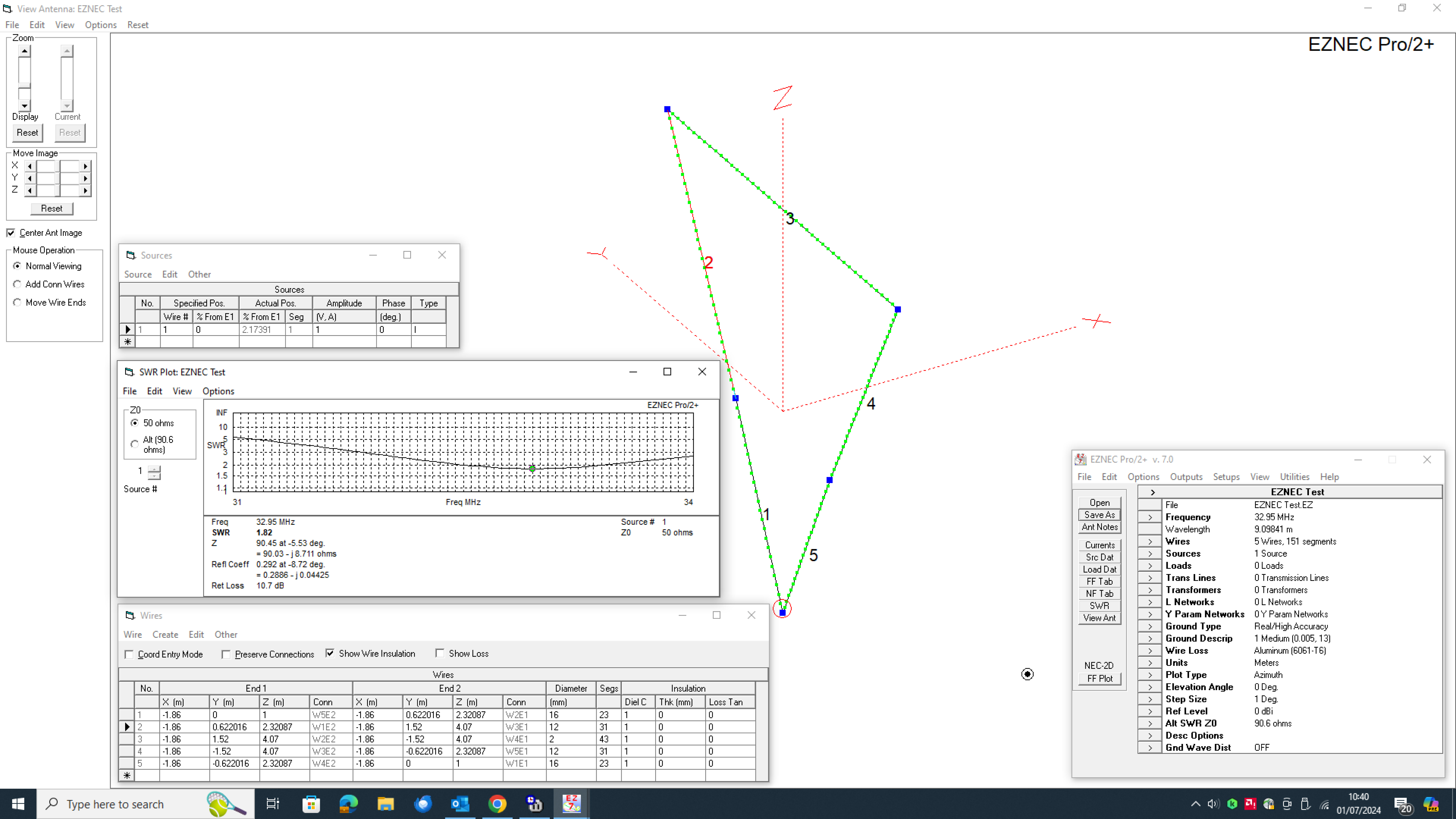
Based on the model, the ‘Dip’ should occur in or around 32.95Mhz but with the actual build – the dip occurred around 31.400MHz – nearly 1.5MHz low
What happens if you build to your model?
So, something odd is going on, but may be to do with a combination of things. EZNEC [NEC/2 calculating engine] is well documented on the subject when wires join at acute angles and the tapered wire modelling.
All elements are as per the EZNEC model. Diameters and lengths are all correct. ‘Wire Loss‘ is set to aluminium 6061-T6. However EZNEC allows you to set the wire loss of each wire individually which we did, setting the the top wire as ‘Copper‘. However this revealed no perceived change in resonant frequency. Given this scenario – what if we want to build a multi-element beam antenna? If you use the same ‘reasoning’ as above and build your antenna based on the ‘model’ then you’re going to get real-world results that are wrong.
How did we stumble upon this?
When I built my first test Delta Loop, it was modelled in EZNEC+ and built exactly to the model. It was a 2 element for the 10m band using the same alloy stock and ‘Flexweave’ top wire as the above example. The element clamps were the ‘Green’ polypropylene from ‘Stauff’ rather than the black ‘Polyamide’ ones which contain a certain amount of carbon and [?could] potentially alter the resonant frequency. Following construction, an antenna analyser was connected to the feed point. No matching device was used as I wanted to see the generic natural response of the antenna.
When an analyser sweep was performed, the array was resonant about 1.3MHz low which I thought was odd. Front to back testing was performed on a field strength meter located behind the antenna. It was very apparent that the front to back on the antenna was poor at the desired frequency, but improved as you moved lower down the band.
Following further builds, it quickly became a problem that ALL live builds suffered from this ‘feature’. So, I approached the issue from a different angle. I had faith in the model – it’s just that the frequency was wrong in the live build.
The Solution – A correctly working loop
After some experimenting and looking at the options, we found a solution – here’s the steps.
You will need EZNEC [available free from W7EL] to build your model, an antenna analyser and an optional field-strength meter for the build.
For those who need a ‘Base’ model to play with, here’s a 6m 3 element delta loop.
It can be used for starters as EZNEC allows you to ‘scale’ the wires – so it’s easily changed to suit other bands. You can duplicate elements and use this as a starting point for your model.
‘EZNEC’ Software Actions
1 – Design your model in EZNEC as you would normally do
2 – When the model is completed, save a duplicate version – call it ‘dev’ or similar
3 – Let’s presume we are building a 4 element loop. Open your ‘dev’ model file
4 – Remove all elements from the model except the ‘Reflector‘. Connect a source at the feed point as EZNEC needs one to perform a sweep
5 – Run the sweep and note the ‘dip’ frequency. Don’t ‘Save’ the model – just close it down
6 – Open the model file again. Remove all elements from the model except the ‘Driven Element‘
7 – Connect a source at the feed point as EZNEC needs one to perform a sweep
8 – Run a sweep and note the ‘dip’ frequency. Don’t ‘Save’ the model – just close it down
9 – Open the model file again. Remove all elements from the model except the ‘Director 1‘
10 – Connect a source at the feed point as EZNEC needs one to perform a sweep
11 – Run a sweep and note the ‘dip’ frequency. Don’t ‘Save’ the model – just close it down
12 – Open the model file again. Remove all elements from the model except the ‘Director 2‘
13 – Connect a source at the feed point as EZNEC needs one to perform a sweep
14 – Run a sweep and note the ‘dip’ frequency. Don’t ‘Save’ the model – just close it down
15 – If the antenna is more than 4 elements, do the same for Director 3, 4, 5 etc.
Antenna Build
1 – You now have 4 ‘dip’ frequencies [or more/less depending on the size of your array] noted down based on the sweeps of each element in EZNEC. We found the reflector frequency is centred in or around the required operating frequency
2 – Build the ‘Reflector‘. Ignore the EZNEC element lengths in the model
3 – Using your antenna analyser, build the element to the dip frequency noted in the sweep
4 – Take the reflector off the array and build the ‘Driven Element‘
5 – Ignore the EZNEC element lengths in the model
6 – Using your antenna analyser, build the element to the dip frequency noted in the sweep
7 – Take the ‘Driven Element‘ off the array and build ‘Director 1‘
8 – Ignore the EZNEC element lengths in the model
9 – Using your antenna analyser, build the element to the dip frequency noted in the sweep
7 – Take ‘Director 1‘ off the array and build ‘Director 2‘
8 – Ignore the EZNEC element lengths in the model
9 – Using your antenna analyser, build the element to the dip frequency noted in the sweep
To Note: The important thing here is to build the element to the ‘dip’ frequency. How you build the element is not critical. Use whatever materials you have. You can have various tube diameters and use either bare or coated wire for the ‘top-wire’. It’s the frequency that’s important.
Antenna Testing
1 – Re-combine all elements back in the array. Spacing is as per the EZNEC model
2 – Open the driven element loop and connect a small length of 50 ohm coax to the feed point [crocodile clips may help]
3 – Connect this lead to your antenna analyser
4 – Run a sweep
5 – You should find the natural resonant frequency of the antenna is close to what you expect
6 – If it’s a little ‘Low’ in band, shorten the driven element loop a little until you are happy
7 – Likewise if it’s a little ‘High’, lengthen the driven element loop a little until you are happy
8 – Some models will have a natural impedance close to 50 ohms – if this is the case, then great – you won’t need any matching device. Others won’t – it all depends on your model. If the antenna requires matching, then your best option is to build a gamma match. I used 16mm tube and a section of PTFE as the insert for the Vortex Delta Loops – it handles QRO easily. Don’t use nylon – it’s rubbish at ‘RF’ and will probably melt!
Optional – Front-to-Back Optimising
1 – Purists will want the max front-to-back ratio which normally gives maximum forward gain [or thereabouts]
2 – Open the reflector ‘link wire’ at the base.
3 – Insert 2 parallel ‘Stiff’ copper wires about 15cms/6 inches long
4 – Using 2 crocodile clips and a small length of wire soldered between the two clips, short out the parallel wires starting at the feed point
5 – Take note of the field strength meter reading
6 – Move the clips downwards about 1cm/half an inch at at time. Check the field strength meter reading each time
7 – The task here is to get the ‘minimum‘ reading on your field strength meter.
8 – If you find that the the field strength increases as you move the clips down the wires, then the loop is too large and you’ll need to decrease it slightly. Sliding one of the vertical tubes in a few cms/inches each side does the trick. Re-do the exercise and take new readings.
9 – When you find the ‘sweet spot’ [lowest reading on the field strength meter] – that’s the maximum front to back
10 – You can then ‘Hard Solder’ where the croc- clips were attached with a copper wire
11 – Don’t change the length of the other elements – only tune the reflector for front-to-back
Job done – enjoy your new build!

