Build a Great Lightweight 15m 3 Element Yagi
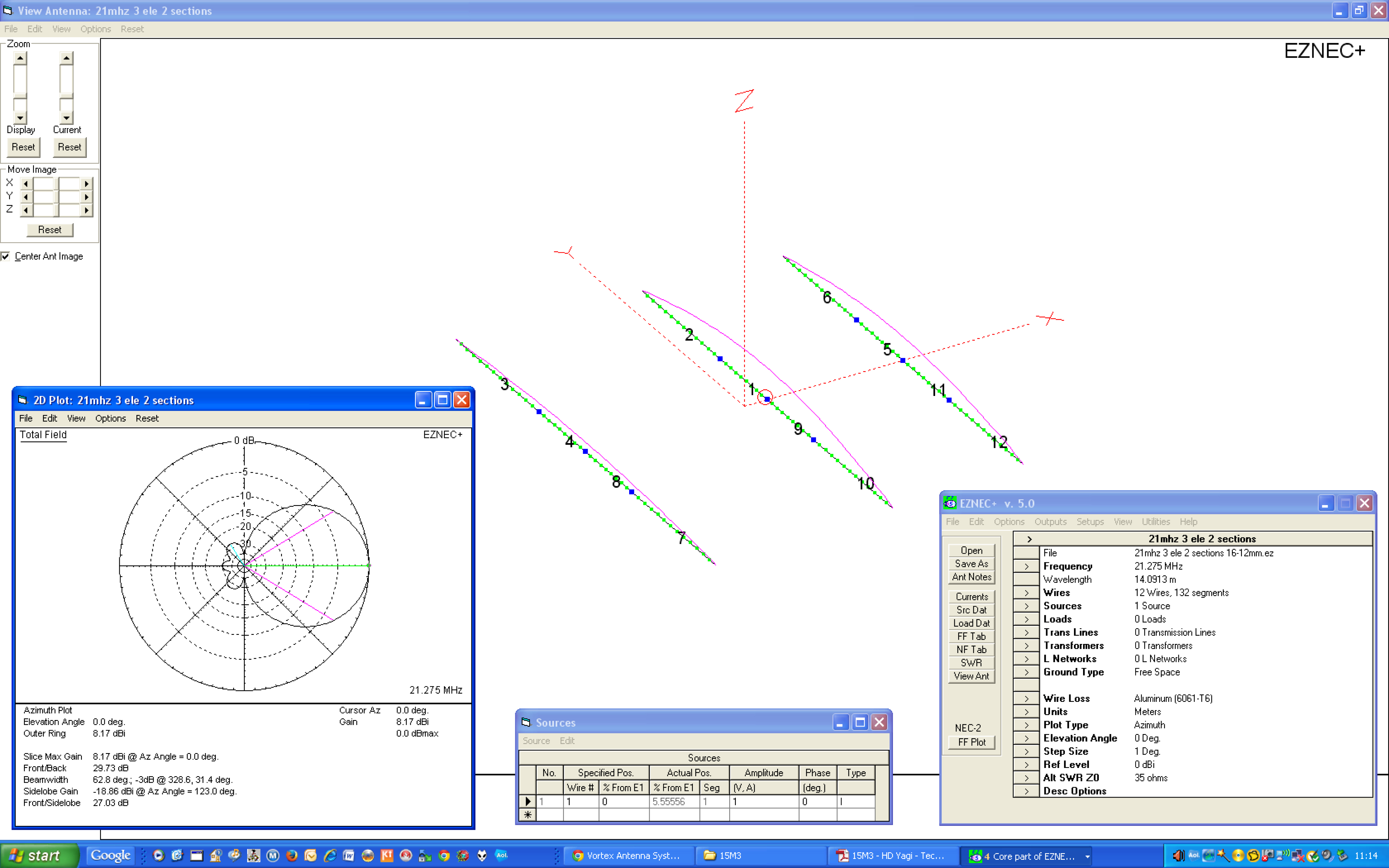
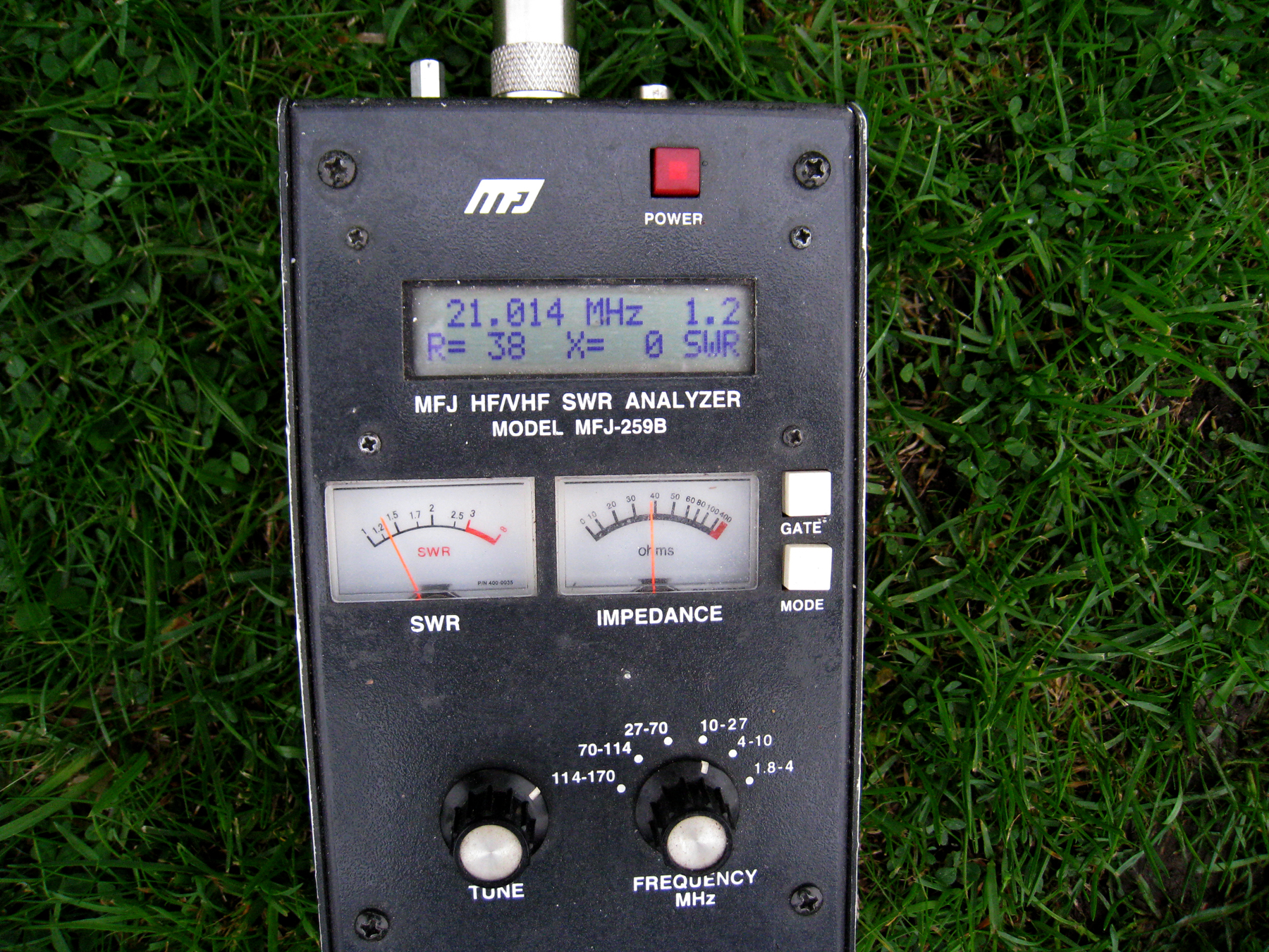
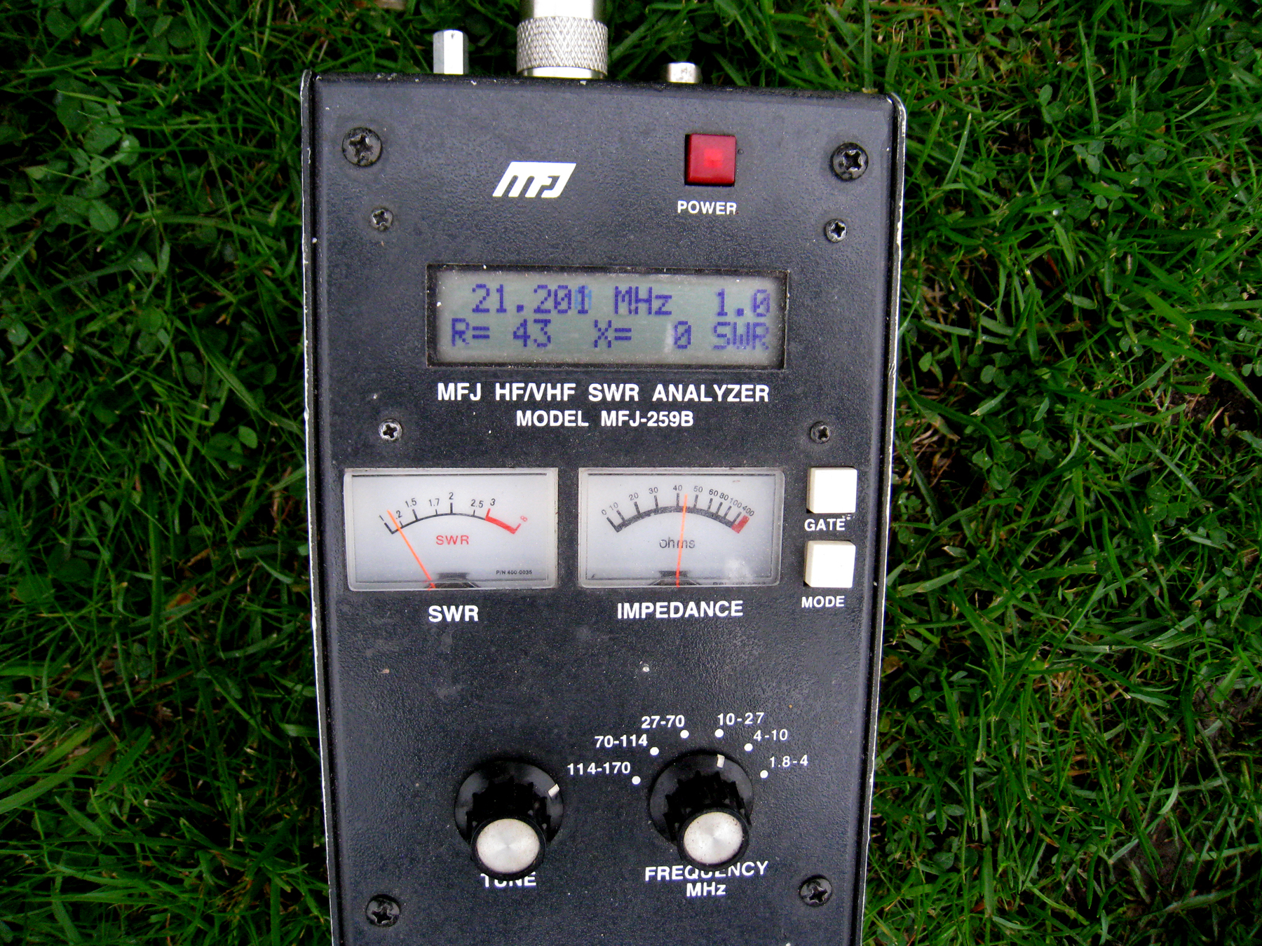
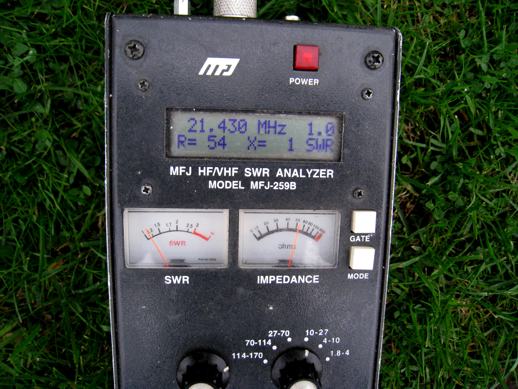
Here’s a simple and very effective lightweight Yagi build for 15m. Sporting a forward gain of nearly 8.2dbi and 30db front to back, this is a nice personal design by Steve G0UIH [originally for Vortex Antennas]. Bandwidth is also excellent as the driver is pushed forward slightly, offering no more than a 1.2 to 1 SWR over the full 450KHz of 15m – so is ideal wherever within the band you operate.
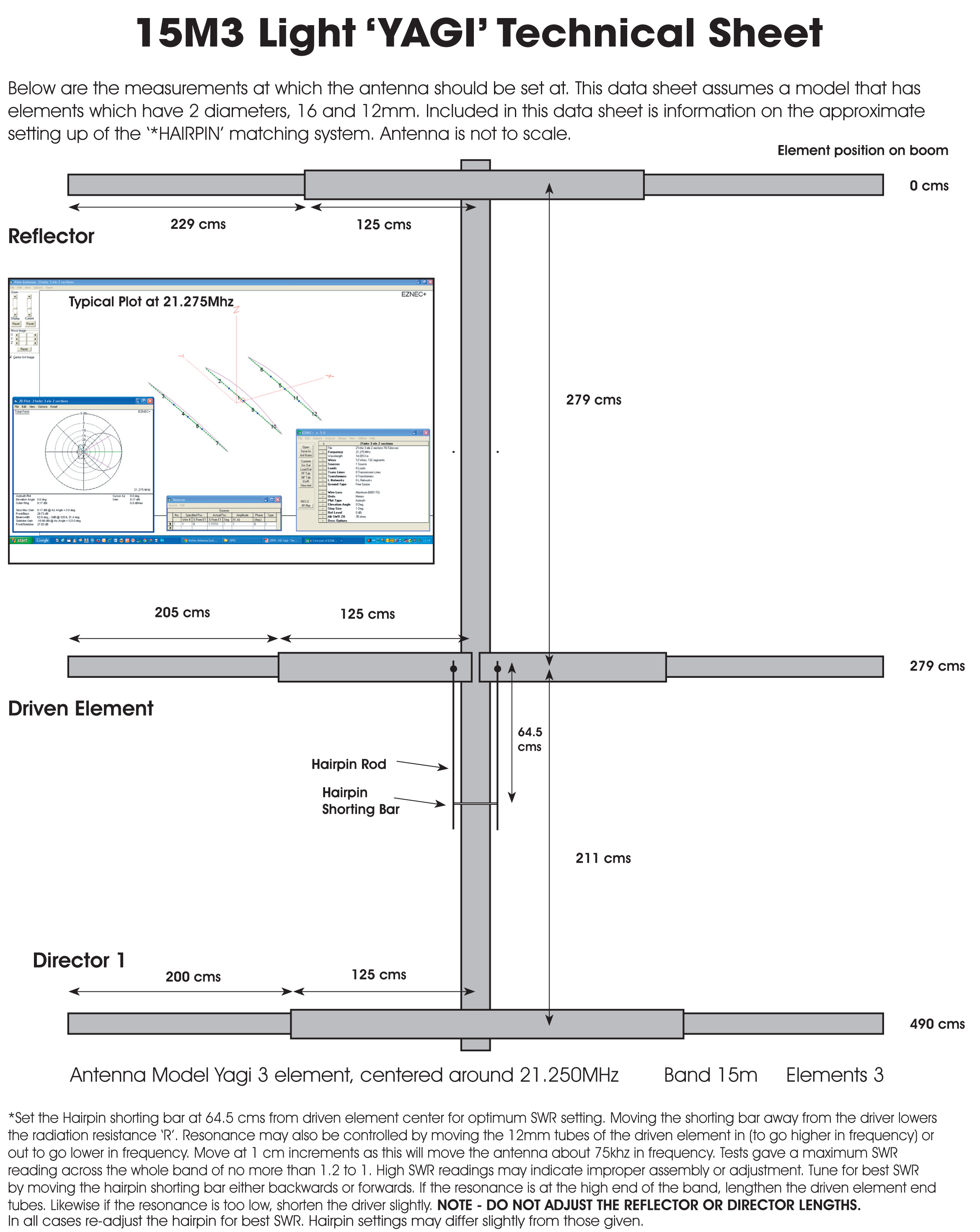
The design is also very lightweight, making use of 16mm and 12mm diameter tubes. Alternatively, constructors can use 5/8th x 16 Gauge tubes for the inner sections – so the array is easily constructed.
As an added advantage, I modelled the array based on using a maximum boom length of 5m. This is a typical size which is available from the majority of trade/consumer outlets such as ‘Simmal‘ and ‘Aluminium Warehouse‘. This means you DONT have to cut the boom which is a real bonus. Just follow the data sheet and you’ll be up and running pretty soon.
Click on the image below for a hi-res PDF of the plot
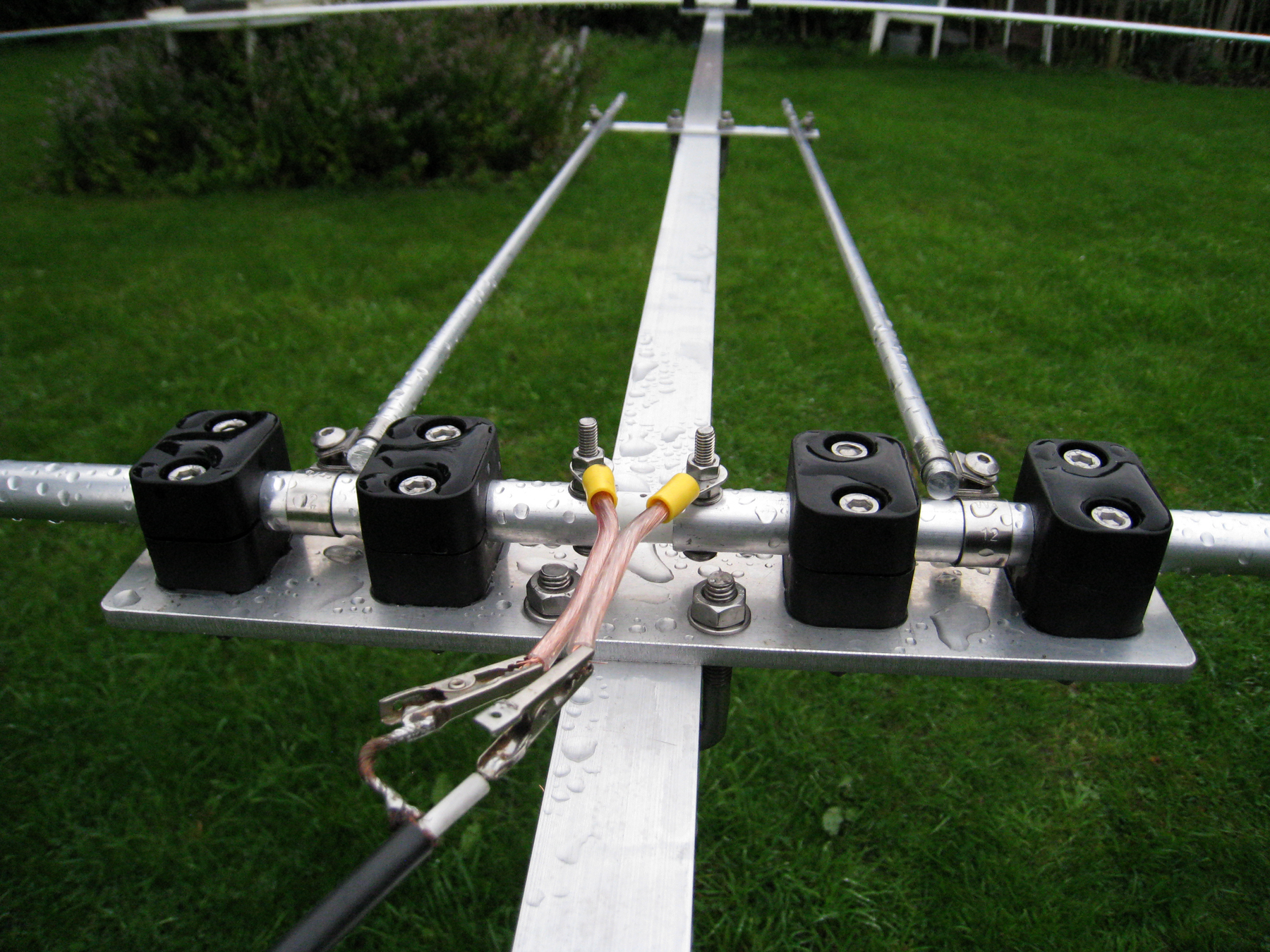
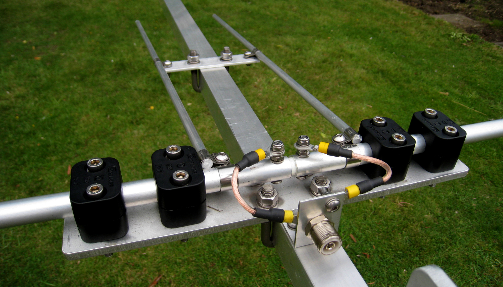
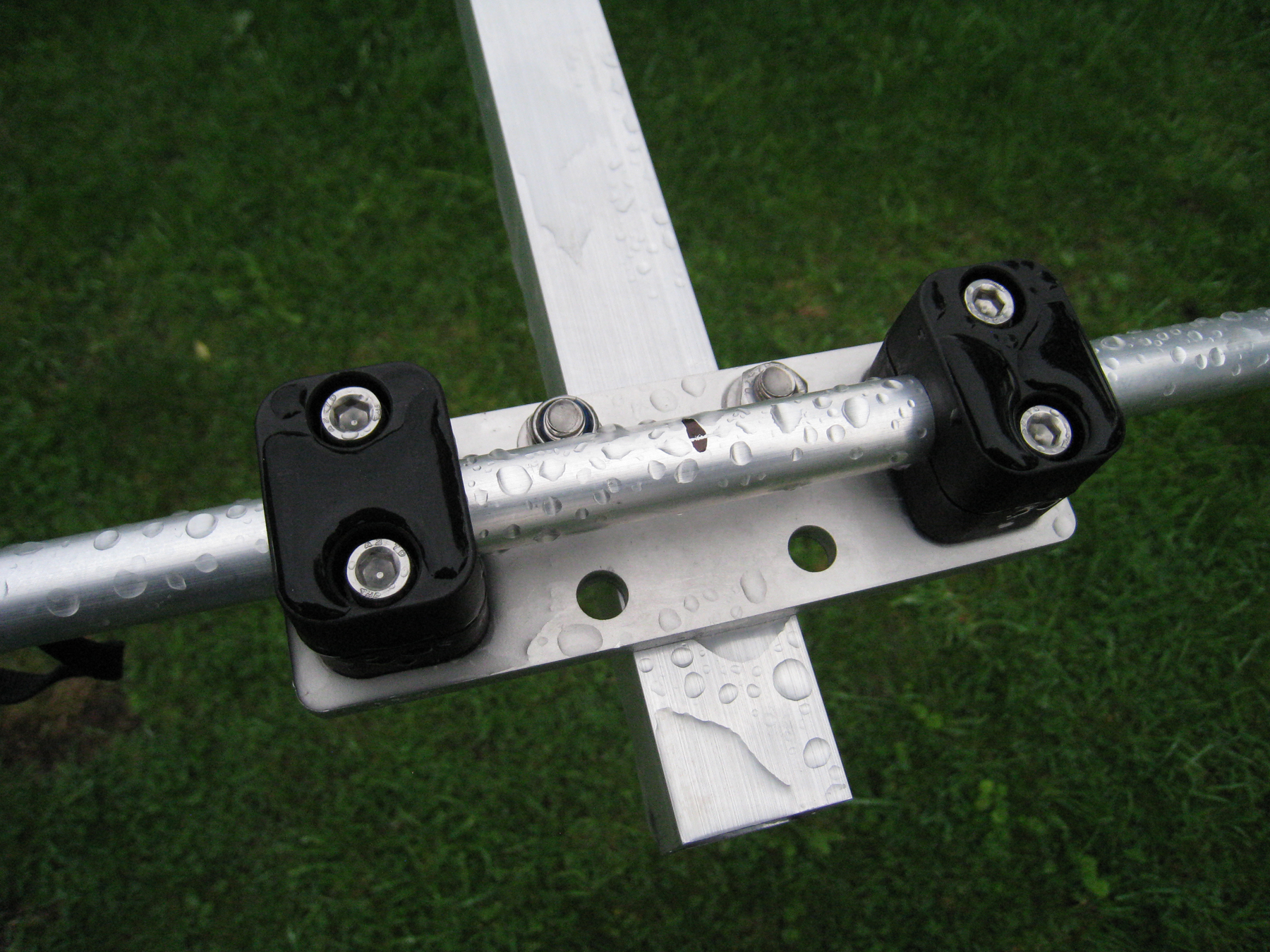
A ‘Hairpin Match’ does a good job in matching the array. The driver is a ‘Split-Dipole’ design.
The natural impedance of the array is around 30 ohms. In order to match the array to a 50 ohms coaxial feed, a ‘Hairpin Match’ [aka ‘Shunt’] is used. Hairpins are extensively used when matching Yagi’s and provide a great low-loss solution. The centre of the dipole driven element as shown above is split. A gap of around 1 to 1.5 cms is normally adequate and a fibreglass rod makes a good sturdy spacer. Connect one side of the dipole to ‘Earth‘ and the other to the main ‘Centre Feed‘. It doesn’t matter which way round they go, only that they should be isolated from the SO239 socket to the dipole centre.
The hairpin match uses two parallel rods running adjacent the boom. The rods are then ‘Shorted‘ by a small bar which is adjustable. They are held in position by back-to-back #5 Mikalor stainless clamps. Constructors can slide this bar up and down the rods to get the best match. Start with the shorting bar about 40 cms from the element centre and slide outwards [away from the element]. The SWR will improves as you slide the bar. When all is good, secure the bar with a square section U-Bolt and tighten up the Mikalor clamps.
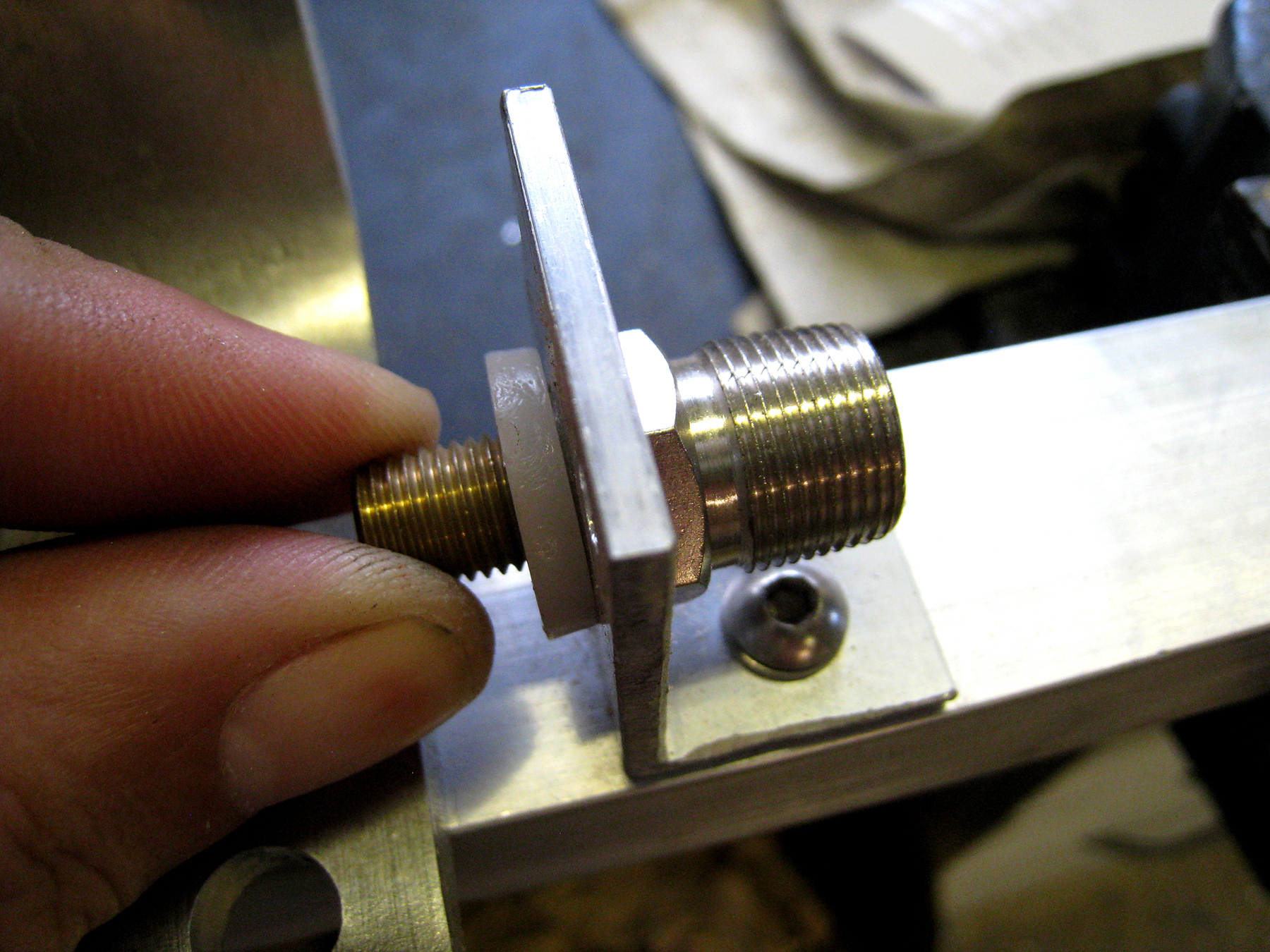
Don’t forget to include the nylon isolating spacer as the ‘Center’ needs to be isolated from earth and they shouldn’t touch!
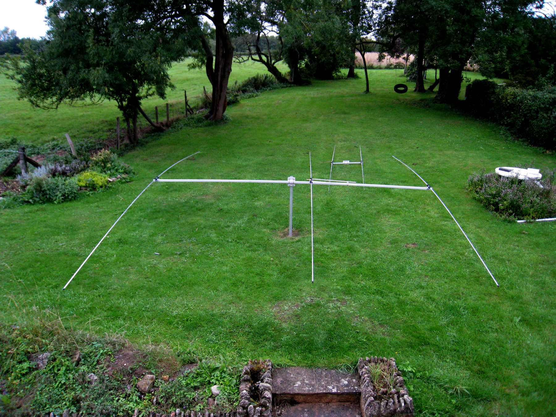
For this project, we used a 1.5 inch x 1.5 inch x 10 Gauge x 5m length square section aluminium boom which is normally the maximum you’d be able to obtain. There will be a small amount of sag at the boom ends, but not enough to require any bracing or support.
The 3/8ths stud mount hardware can normally be located on eBay or at radio/communications outlets such as ‘Rocket Radio‘.
Click here to download an EZNEC file of this antenna
Click on the image below for a hi-res PDF data sheet
Note to Constructors: The EZNEC file shows the driver end-tips at 2.13m. However, the lengths of the leads from the SO239 socket to the dipole centre need to be taken into consideration. Set the end tips at 2.05m [205cms] which will allow a few cms. You can of course set the array for your optimum operating within the band, but we found 2.05m about the ‘Sweet-Spot’.