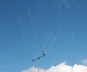
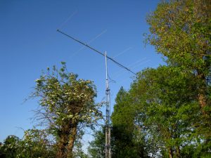
A 7 Element 2m OWA Yagi for FM/Repeater
There’s a few online articles showing build info on small boom 2m band VHF Yagis, Normally these are designed with 144-145MHz in mind for operating in the CW or SSB portion of the band. Saying that, I’ve had a few emails in the past asking about building a nice antenna that could be effectively used for FM or repeater use, centered in or around 145 to 146MHz.
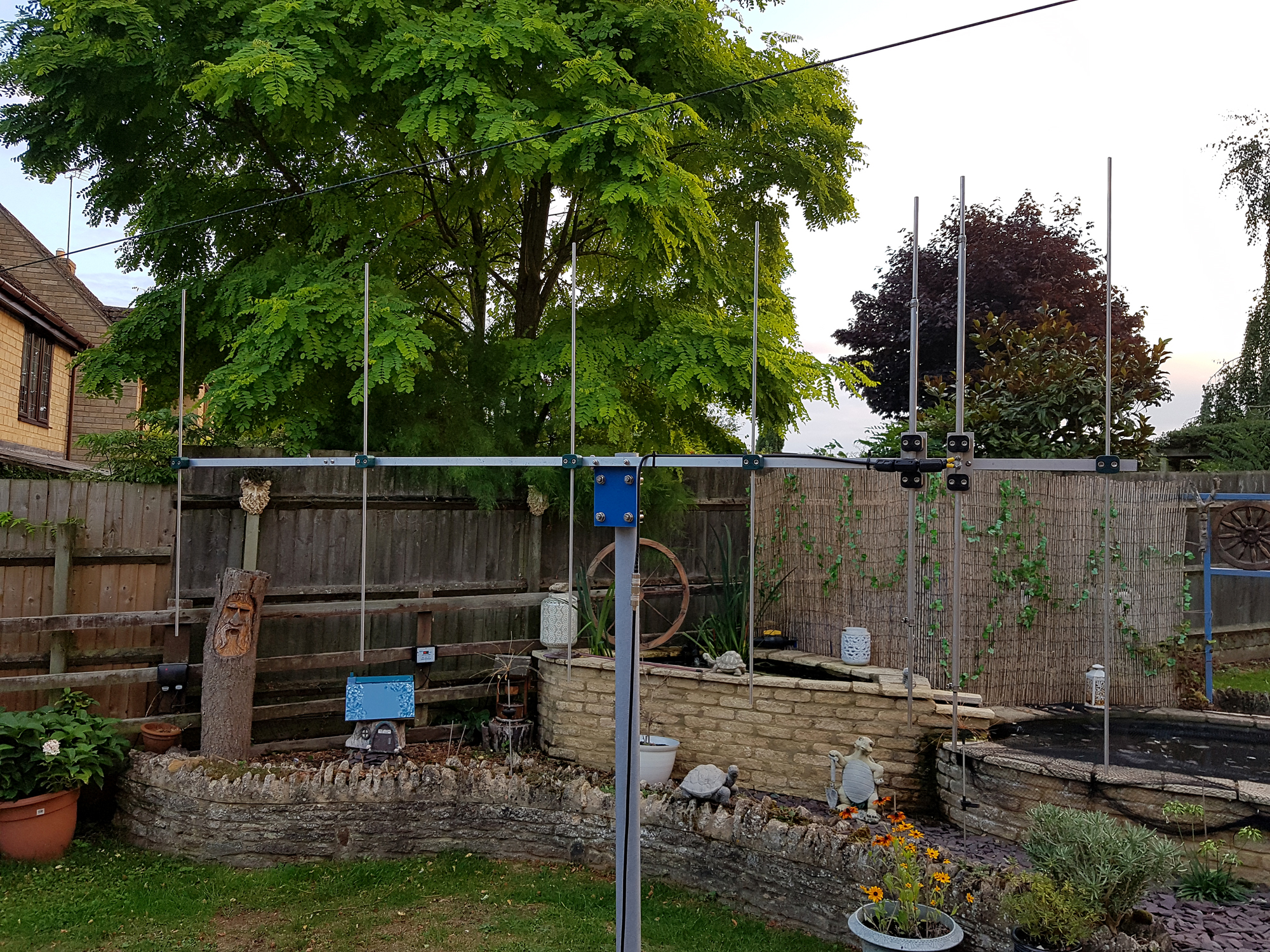
Some users [like myself] – live either in poor VHF locations or are situated in fringe areas, often struggling to hit even the closest repeater. This antenna has an excellent gain of over 11.7dbi and has a very clean pattern with excellent rejection of 35db off the rear with a boom length of just over 2m. In tests on a 2.5m test pole, an S9 ‘forward facing’ signal was unreadable when the antenna was turned 180 degrees.
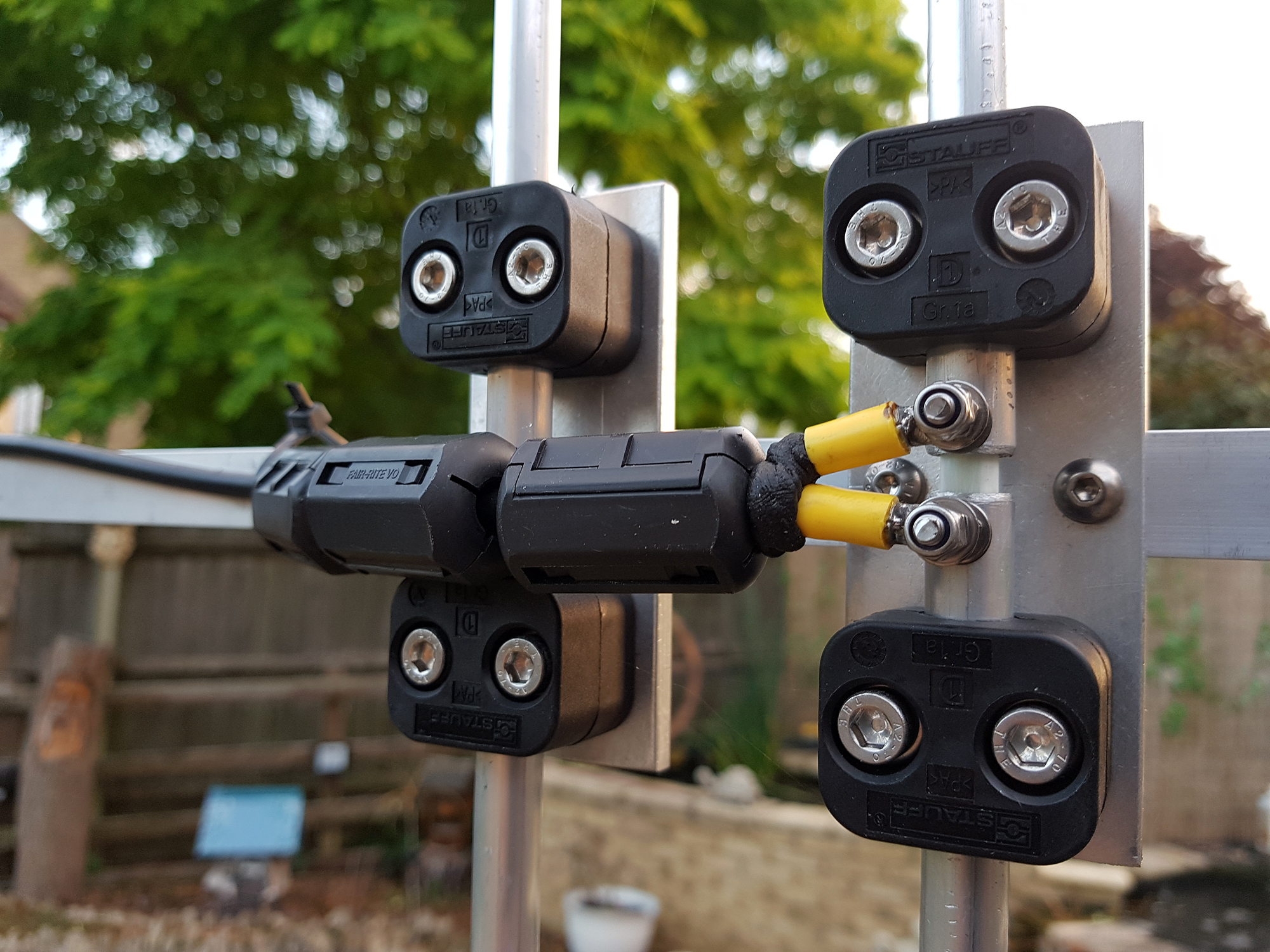
The antenna is a nice OWA [Optimised Wideband Antenna] design that’s got a fairly flat SWR from 144 to 146Mhz. The design here is focused around 145 to 146Mhz so great for FM simplex or repeater work.
We’ve also included 3 x Type 61 ferrite snap-on cores [available from RS Components] at the feed point. These make excellent VHF suppression chokes and in this application act as a choke balun, preventing RF radiation coming back down the feed line.
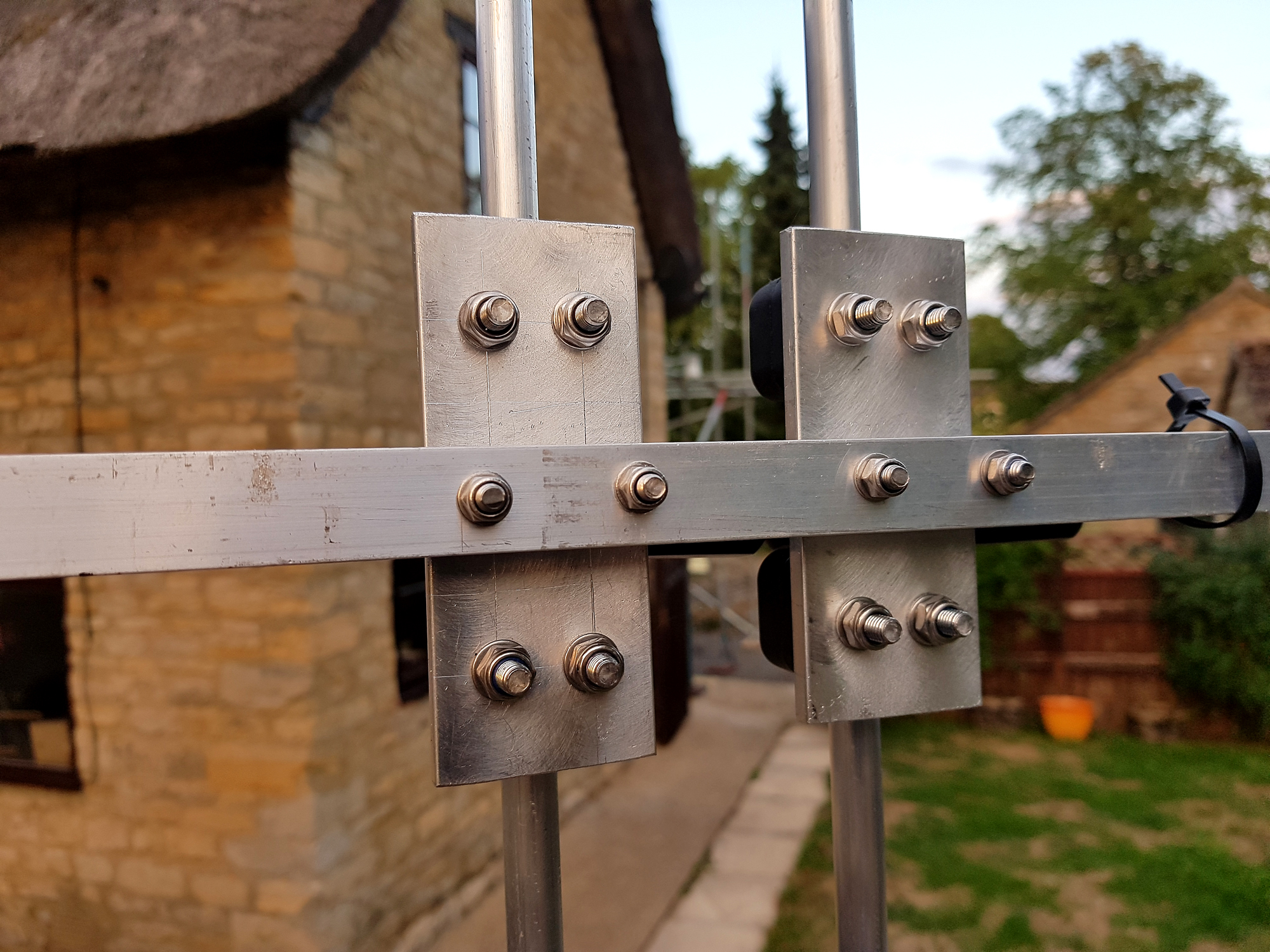
A budget of around £80-£90 should see you up and running which is about half the cost of a much flimsier commercial alternative [and we’ve seen a few rubbishy ones around]. We’ve made this from 3/4 inch box section aluminium with a hefty 3.2mm [10 gauge] wall. There’s no boom sag and the antenna is very sturdy. It’s also pretty well maintenance free.
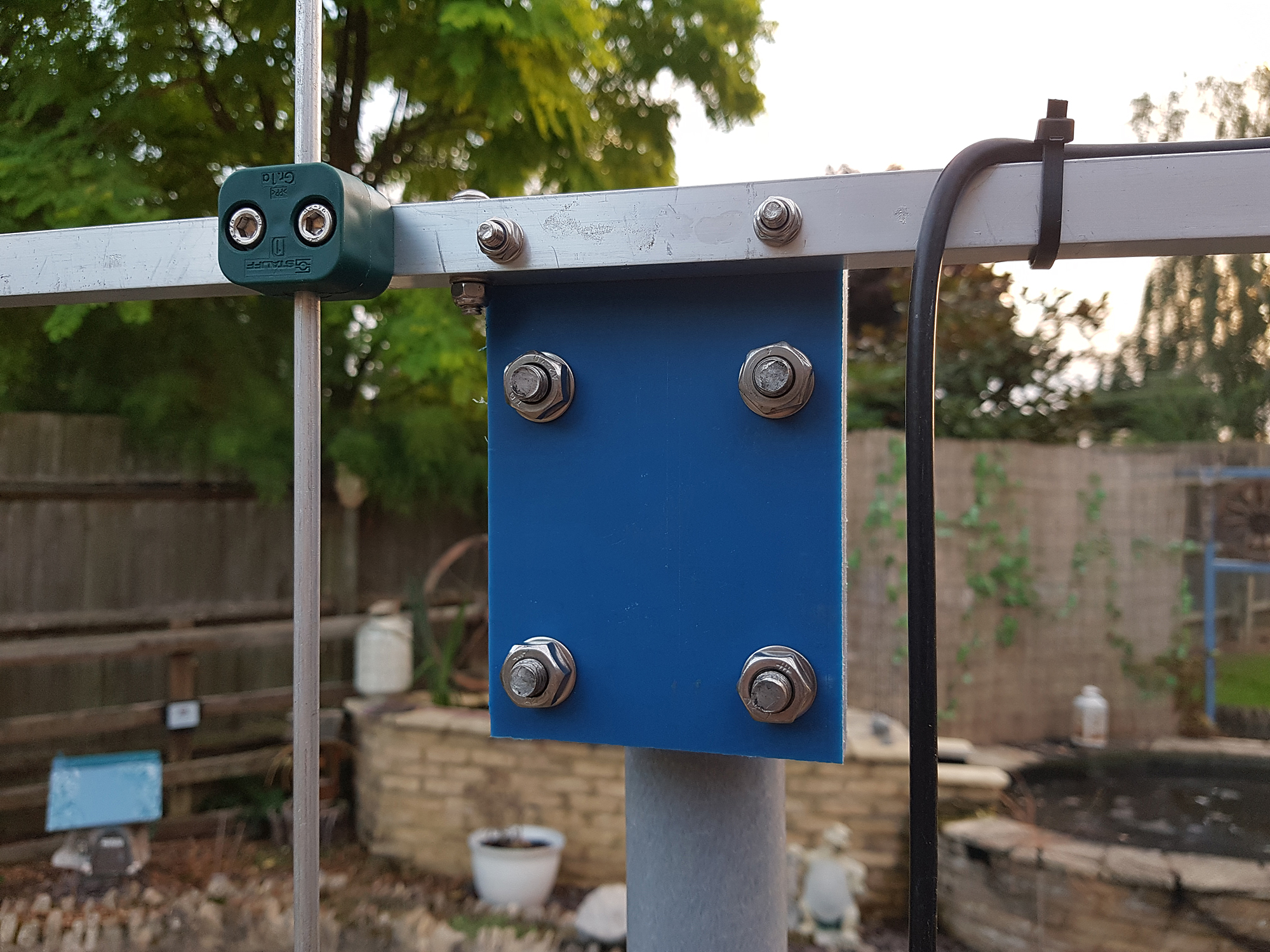
We’d mention and highlight that as the antenna radiates in the vertical plane, the pole [or stub mast] that sits just below the boom should be non-metallic – well at least for about 2 feet or so. Otherwise the metallic mast would act as part of the antenna and could really mess up the radiation pattern. For testing purposes, I used a small section of 2-inch thick-wall fibreglass tube, but a good piece of treated timber would do just as good a job.
I managed to find a small section of thick nylon block in the scrap box which made a good non-metallic mounting plate [although it could be a metal plate as long as you keep it say no more than 6 inches in depth]. A couple of exhaust type clamps finishes it off.
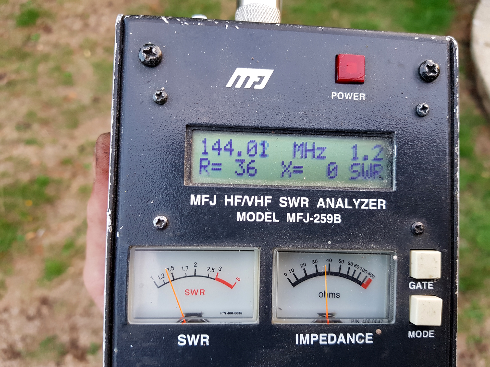
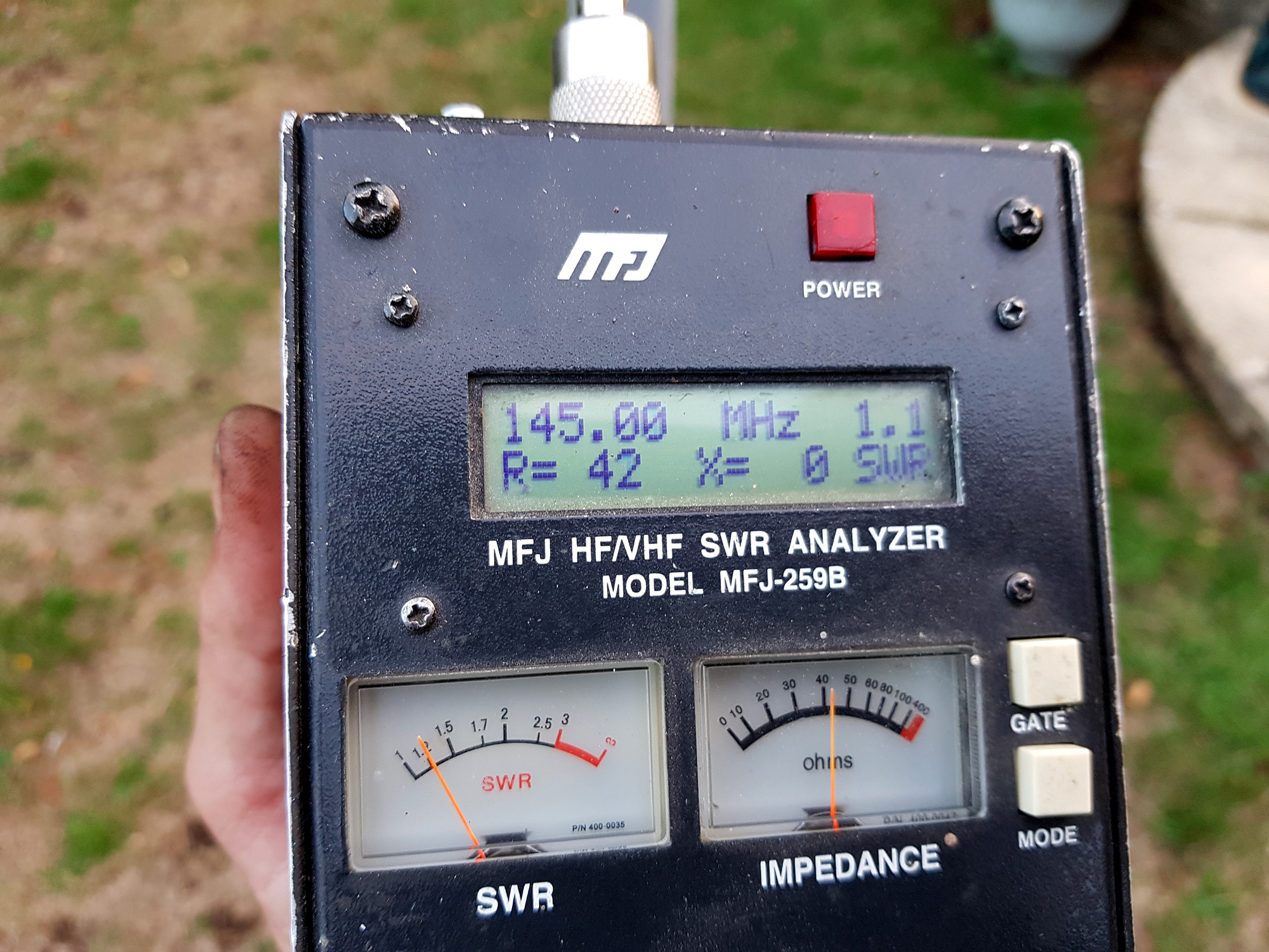
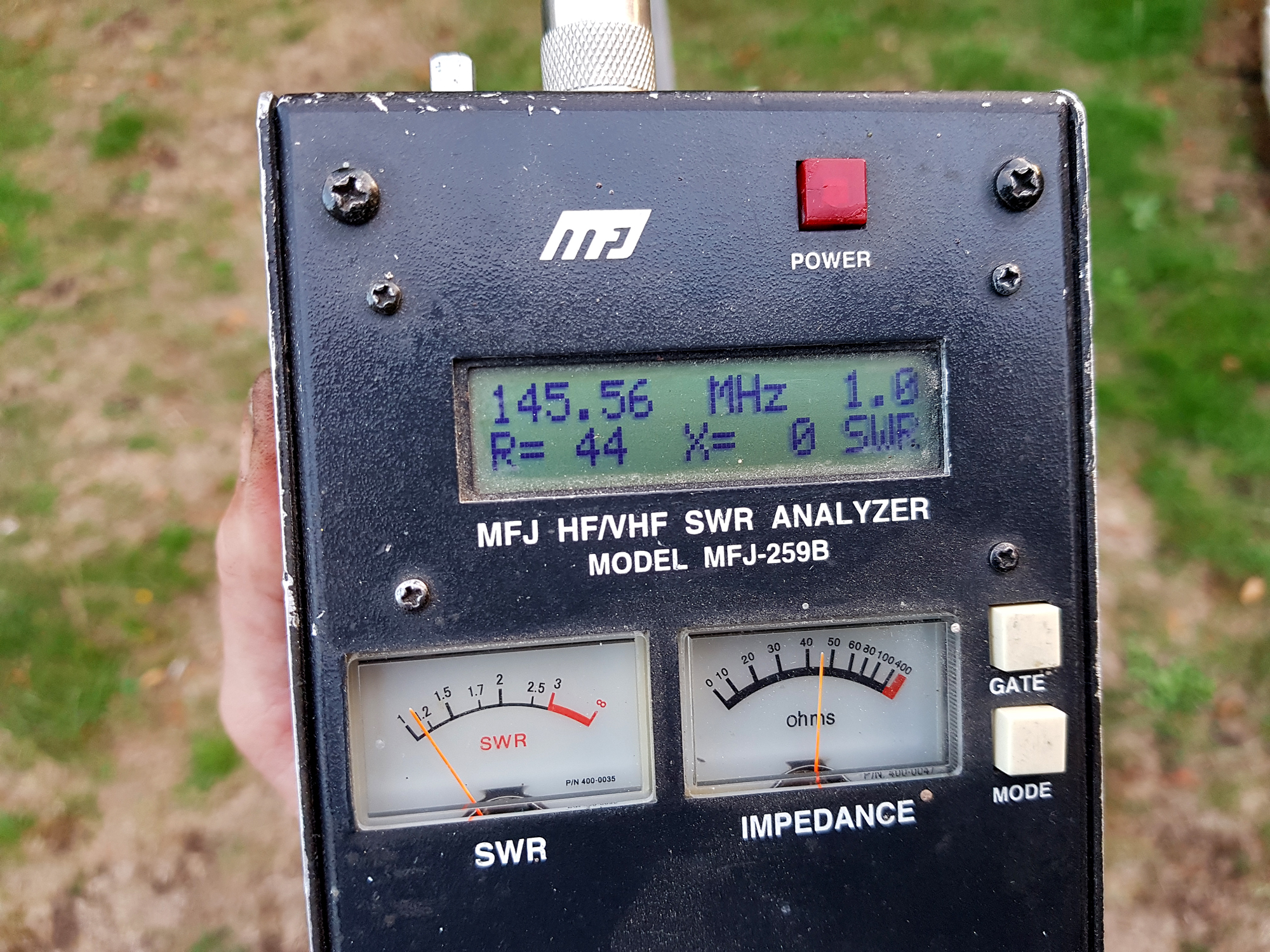
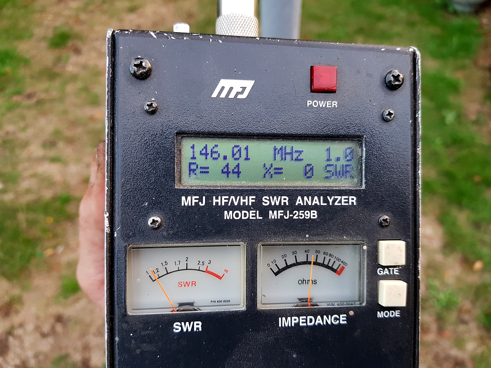
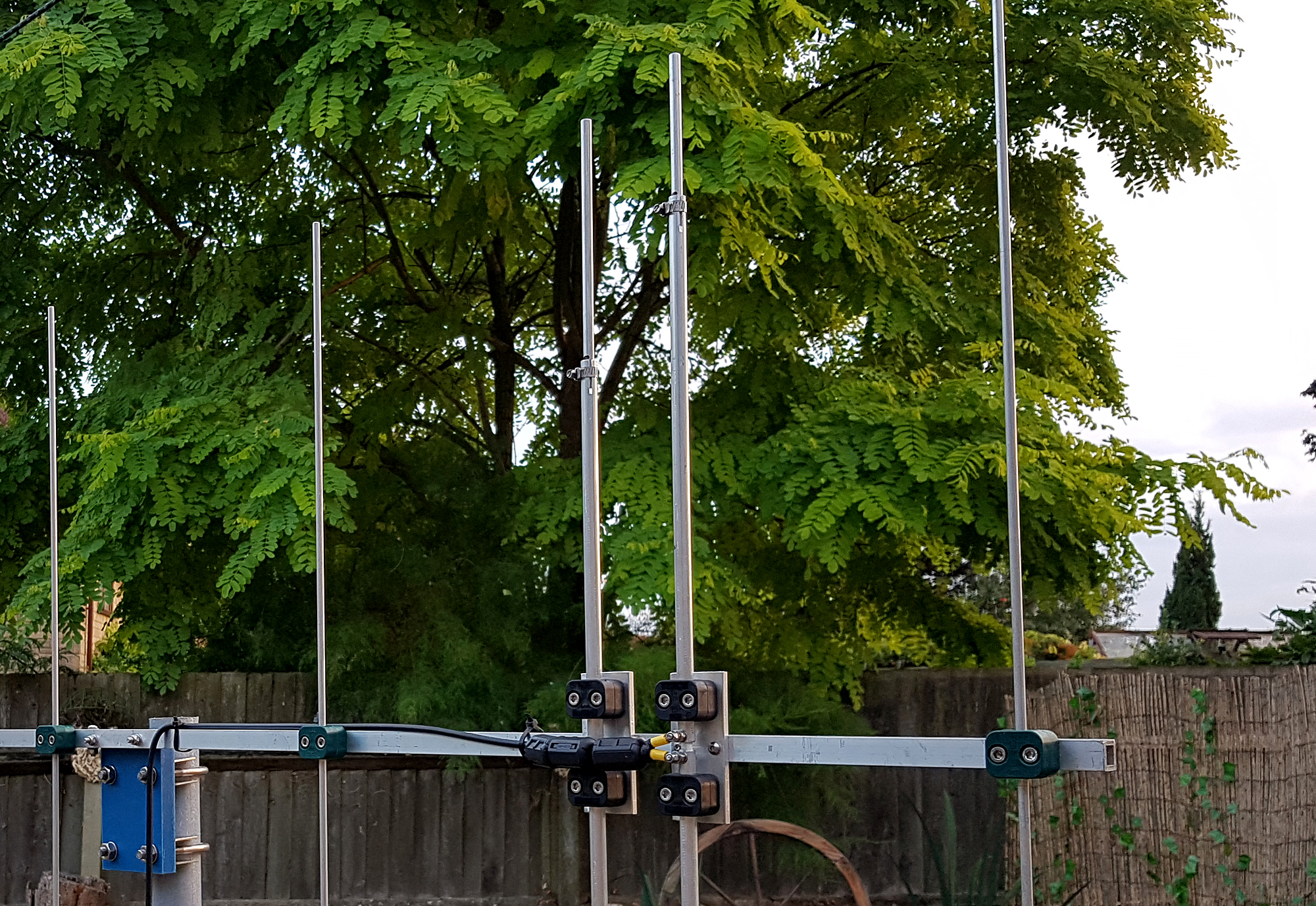
Here’s the data and run down: [Note that the Driver and D1 use 12.7mm [or 1/2 inch] inner tubes and 8mm outer rods that enables the antenna to be tuned – click on the image above for a larger view.
GETTING STOCK:
- 12.7mm x 1.65mm wall Aluminium Tube: Aluminium Warehouse
- 1/4 inch Aluminium Rod: Aluminium Warehouse
- 8mm Aluminium Rod: Aluminium Warehouse
- Stauff Polypropylene Clamps for both 12mm tubes [x4] and 6.35mm tubes [x5].
NB: The 12mm Clamps are quite a tight fit on a 12.7mm tube. Don’t over clamp it up!!
Unfortunately, Stauff don’t manufacture a 12.7mm Group 1A Clamp – but these will work fine for sure! - Boom: 2.5m x 3/4″ x 3/4″ square section x 10 gauge – Aluminium Warehouse
- Driver and D1 Mounting Plates: I used some scrap 1/4 inch ally plates [but you could use anything you have that’s handy]
- A handful of ‘Jubilee’ style or small hose clamps that fit a 12.7mm tube
- M6 Stainless hardware [nuts/bolts/washers etc]
- RG MINI8 Coax [a few feet] or any ‘Premium Coax’ that you have, 1 x PL259 plug and a female to female SO239 adapter. Remember to seal the coax from the weather!
- Exhaust Clamps and Saddles [x2] – to suit your own mounting solution and pole size
ELEMENT LENGTH DATA: [Actual Build – Exposed Lengths]
- Reflector: 1035mm total [1/4 inch aluminium rod]
- Driver: Split Dipole 400mm each side of 12.7mm tube [use a small spacer to separate, such as fibreglass], then *105mm outer 8mm rod [each side]
- D1: 590mm of 12.7mm tube [single section] then *185mm of 8mm rod [each side]
- D2: 934mm total [1/4 inch aluminium rod]
- D3: 924mm total [1/4 inch aluminium rod]
- D4: 918mm total [1/4 inch aluminium rod]
- D5: 880mm total [1/4 inch aluminium rod]
* These are exposed lengths. Cut longer to allow for adjustment.
ELEMENT SPACING DATA:
- Reflector: 0mm
- Driver: 237mm
- Director D1: 315mm
- Director D2: 617mm
- Director D3: 1015mm
- Director D4: 1552mm
- Director D5: 2130mm
Download the EZNEC file here
All-in-all this is a great build, offering excellent gain, pattern and front to back and can be built easily on a reasonable budget. It’s a fairly straight forward project [even for beginners] and is pretty well maintenance free as it requires no matching devices. Everything you need on the hardware side is also linked on this page.
Enjoy your project and if you decide to have a go, then let us know how you got on and we’ll publish your build!
73 – Steve G0UIH – q82.uk

