
An 8 Element Vertical OWA Yagi for 2m
Here’s a nice project that didn’t take too long to make. I decided to put together a dedicated Air-band VHF OWA Yagi on the tower during the summer. At the same time, I removed my old 70cms beam as it wasn’t really getting any use.
Not having much interest in 70cms [and our lousy UHF location] meant I had a space mounting area to put up something small and manageable. Recently, I’ve been chatting more with friends located about 20 miles to the south of me and generally the 2m vertical can be marginal with a couple of the guys, so this antenna has that bit of extra ‘thump’ and is ideal for fringe areas if you’re just struggling just that little bit.
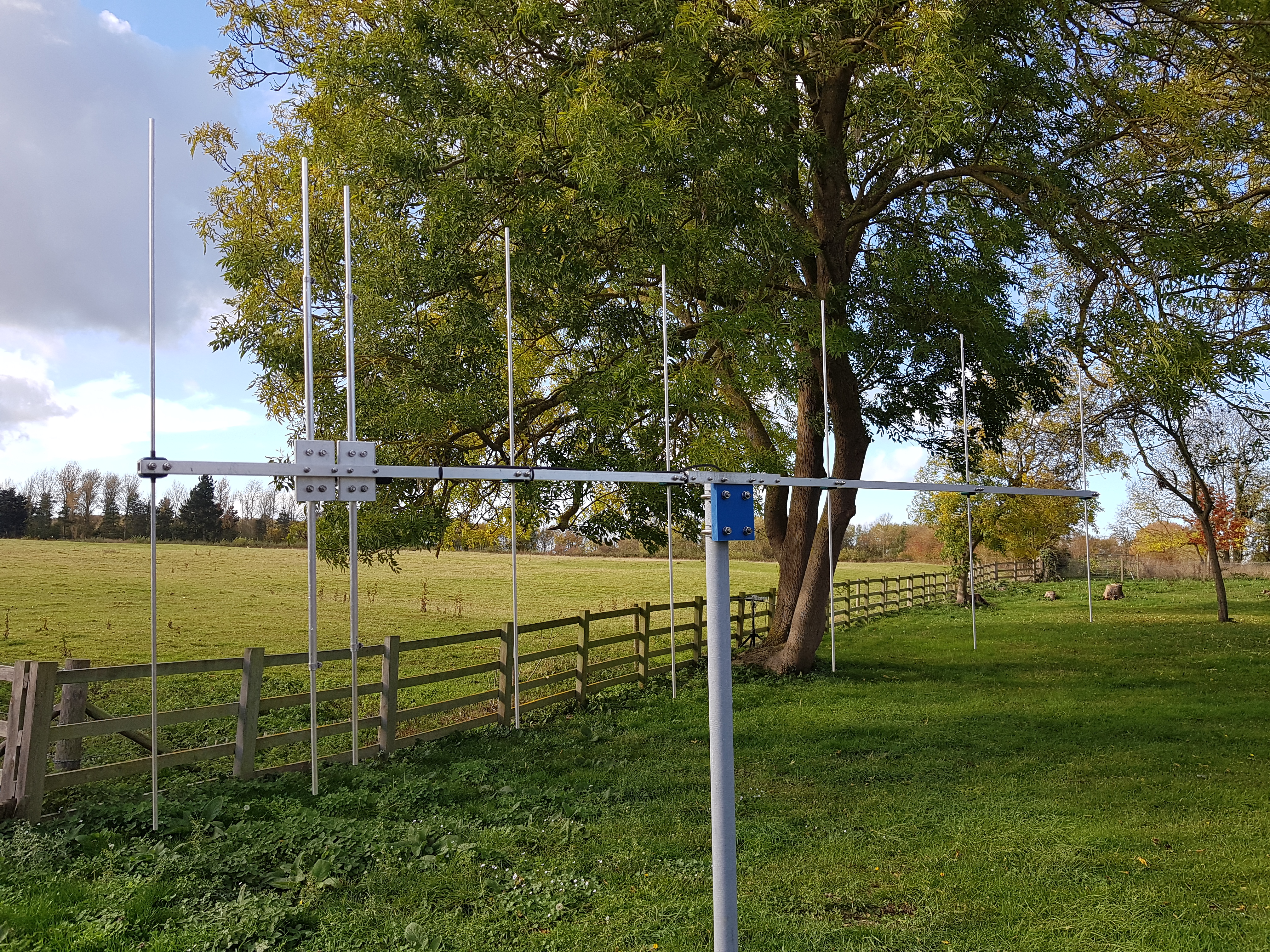
Given this, I checked around the workshop and built this 8 element VHF 2m OWA beam that has heaps of gain and will easily outperform the vertical. The spare position on the tower sits on the left of a ‘T’ section and is fully rotatable.
All I need to do now, is lower the tower and hook up the feeder to the old 70cms coaxial feeder.
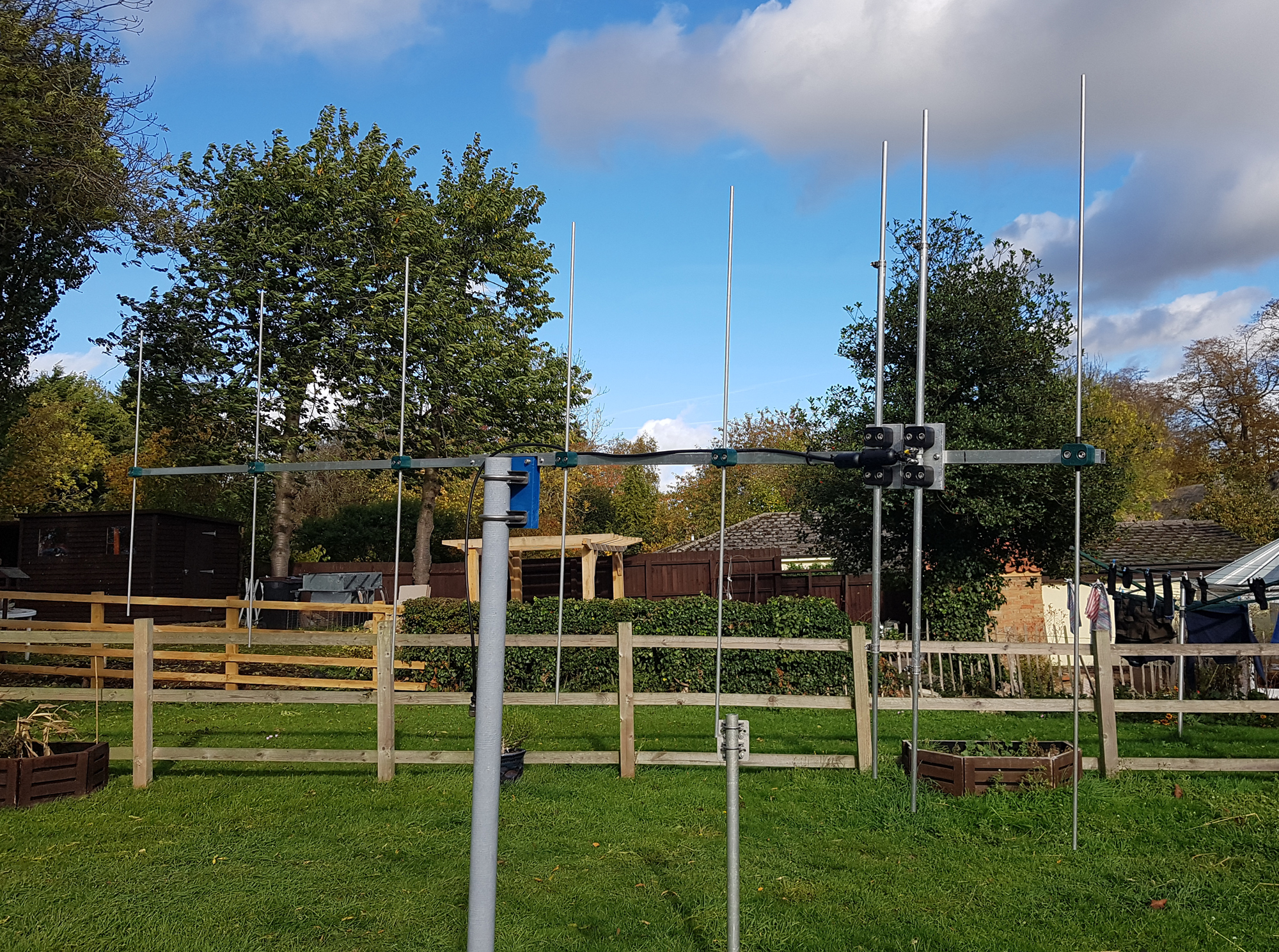
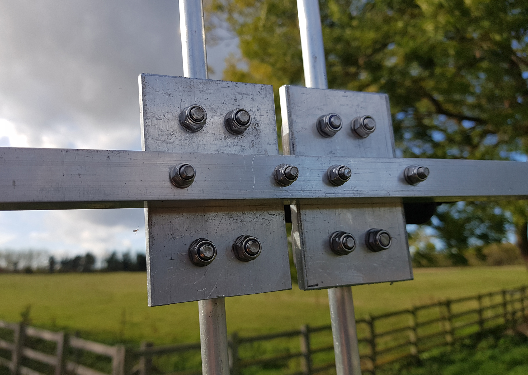
Looking around the workshop I found 2 sections of ¾ inch x 10-gauge square box section that had been cut up for another project a couple of years ago, but never used. Using a small section of ¼ inch angle, I sleeved two box section parts together in order to make a single section boom of just under 3m. There’s no point in wasting old stock, especially as the price of hardware has gone skywards in the past 18 months.
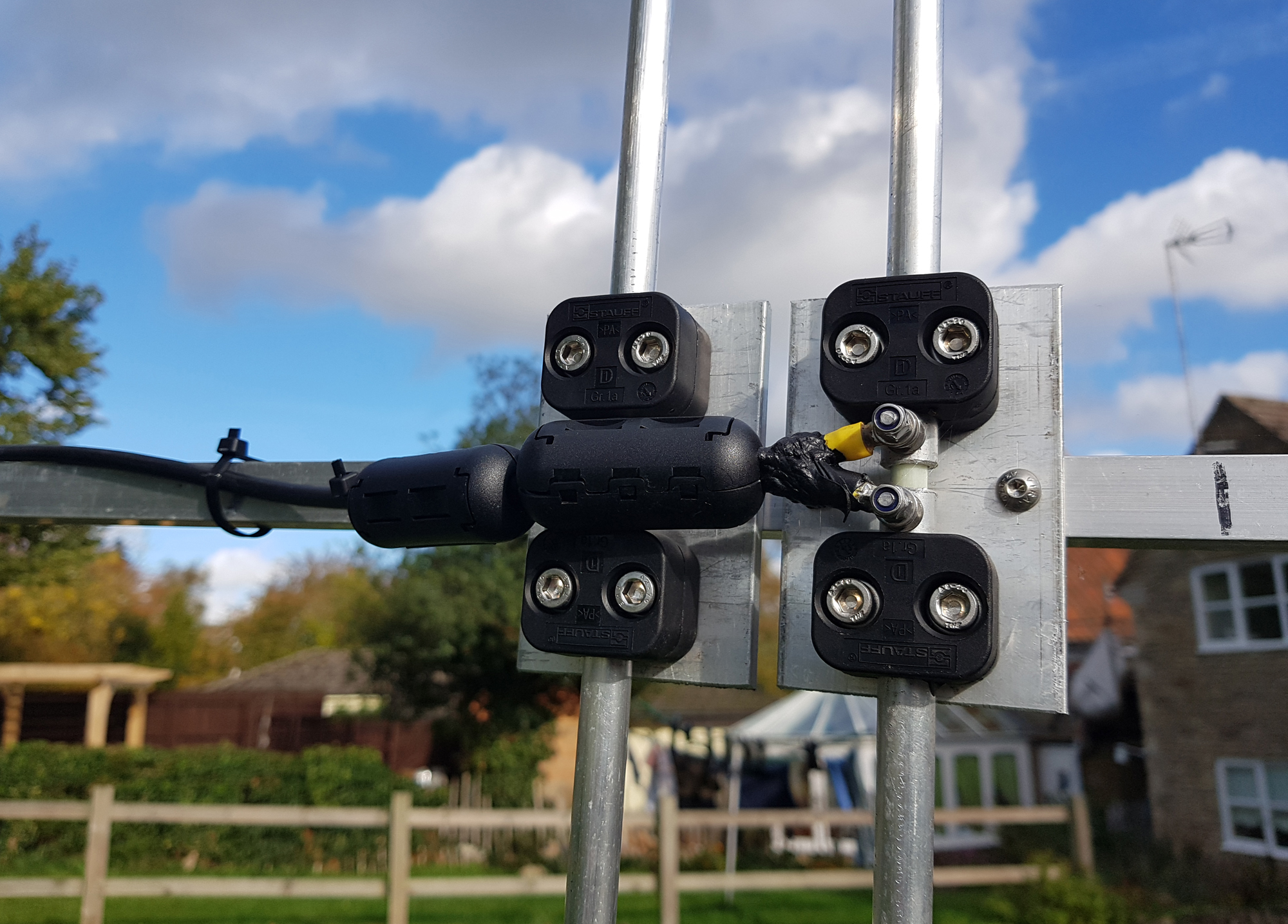
Rather than use any U-bolts for element mounting, I simple cut some ¼ inch plate and drilled permanent M6 holes to mount stainless nuts and bolts to the boom. Simple, easy, cheap and effective.
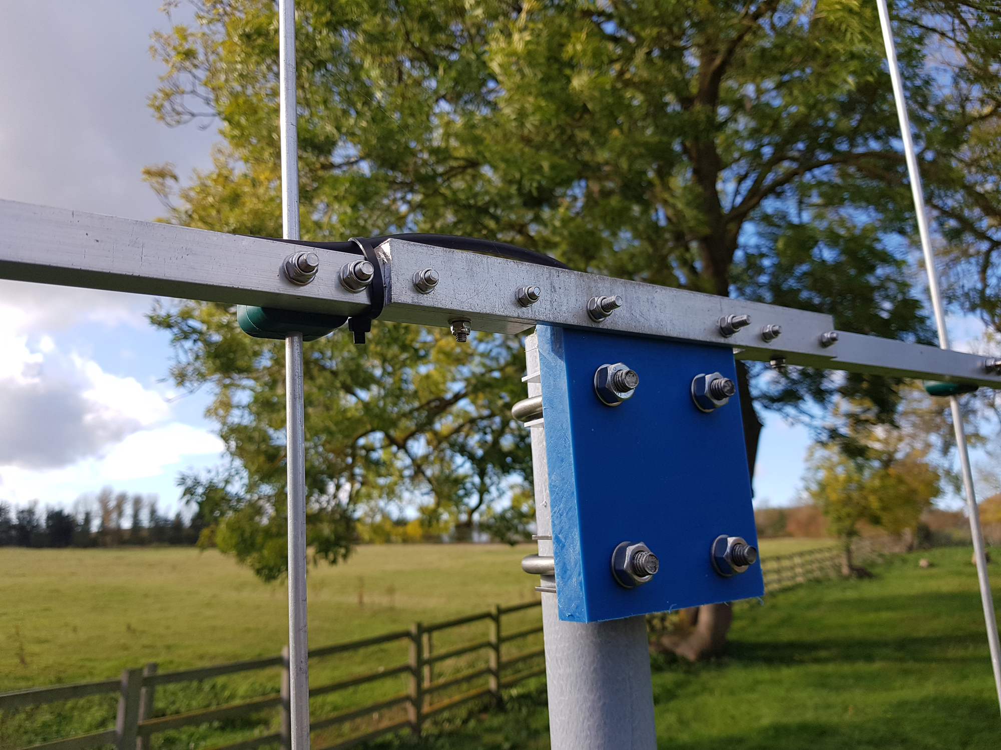
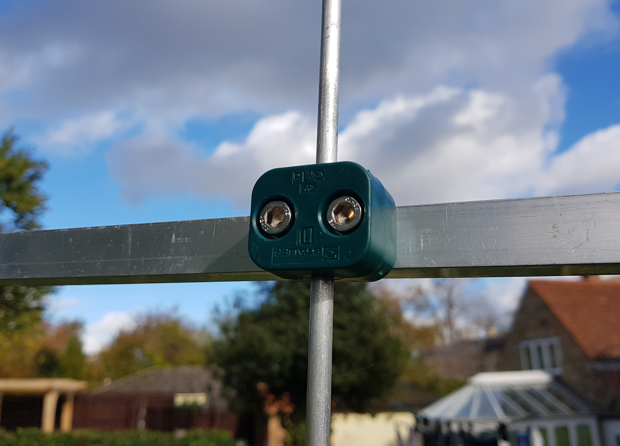
For the element mountings, I used 2 clamps for both the driver and first director as these had slightly heavier duty tubes. For the remaining parasitic elements, single ‘Stauff’ Group 1 clamps were used to secure ¼ inch aluminium rods.
The antenna was built as per the EZNEC model and was found to need no adjustment although as you can see, I modelled the Driver and Director #1 with smaller section outer end rods which would allow for any minor adjustments if required.
As with all beam antennas that operate in the ‘Vertical’ plane, care should be taken when choosing a mounting solution. I’ve chosen the 2-inch fibreglass pole to do the testing, a pole that’s been used previously in other designs.
It’s non-conductive so won’t skew or affect the pattern in any way. When the antenna is placed on the tower ‘T’ section, it won’t have any ‘vertical’ poles or the like in the near vicinity so I’ve no issues in thinking that the results will be very much the same as on the test pole.
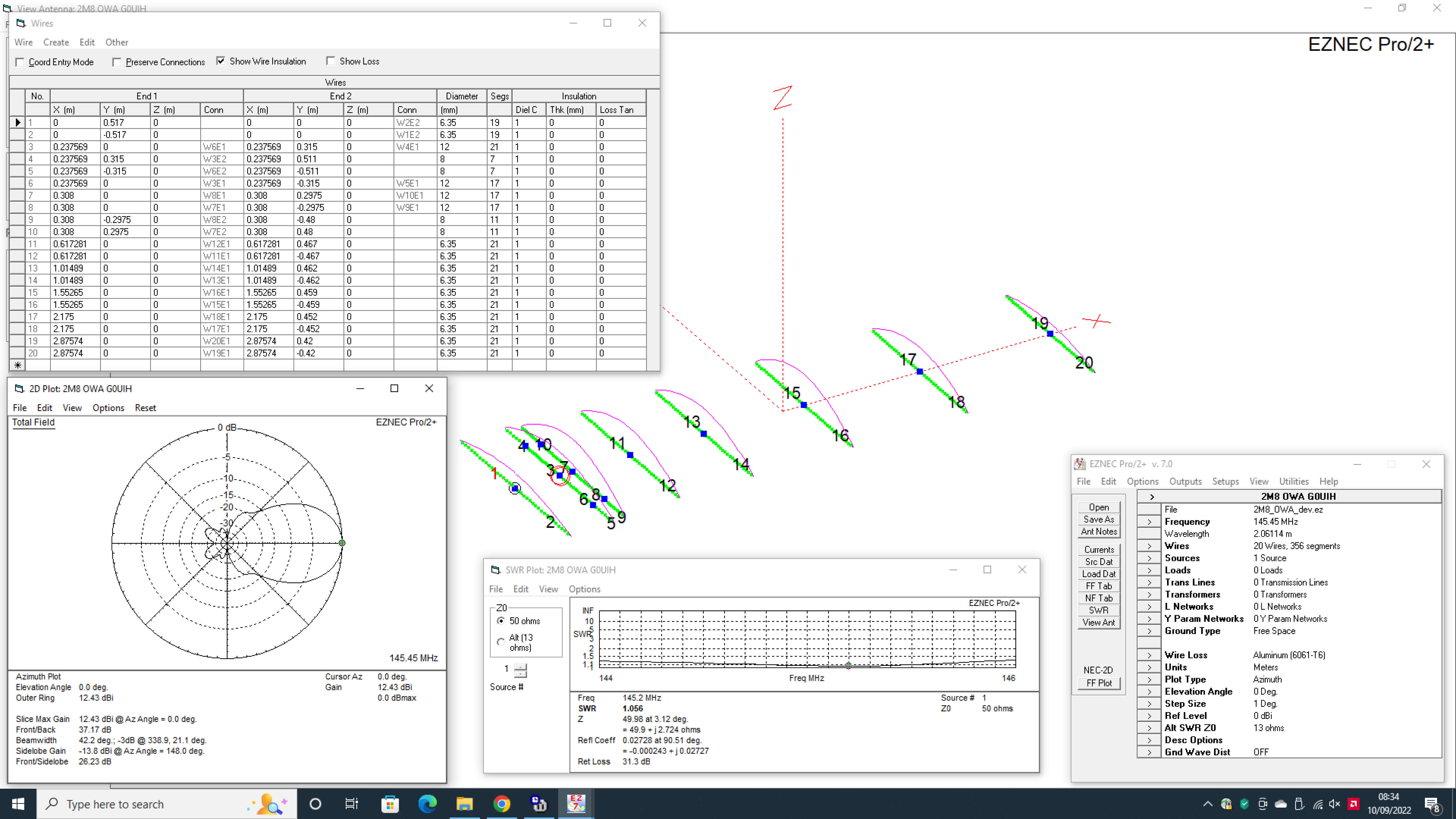
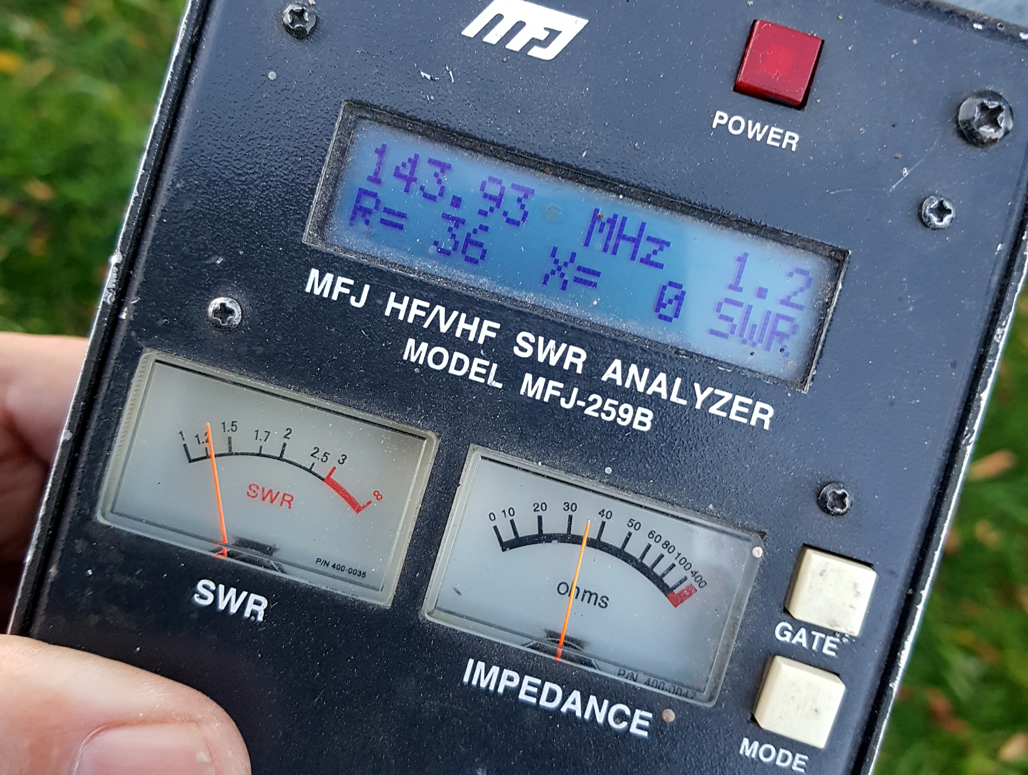
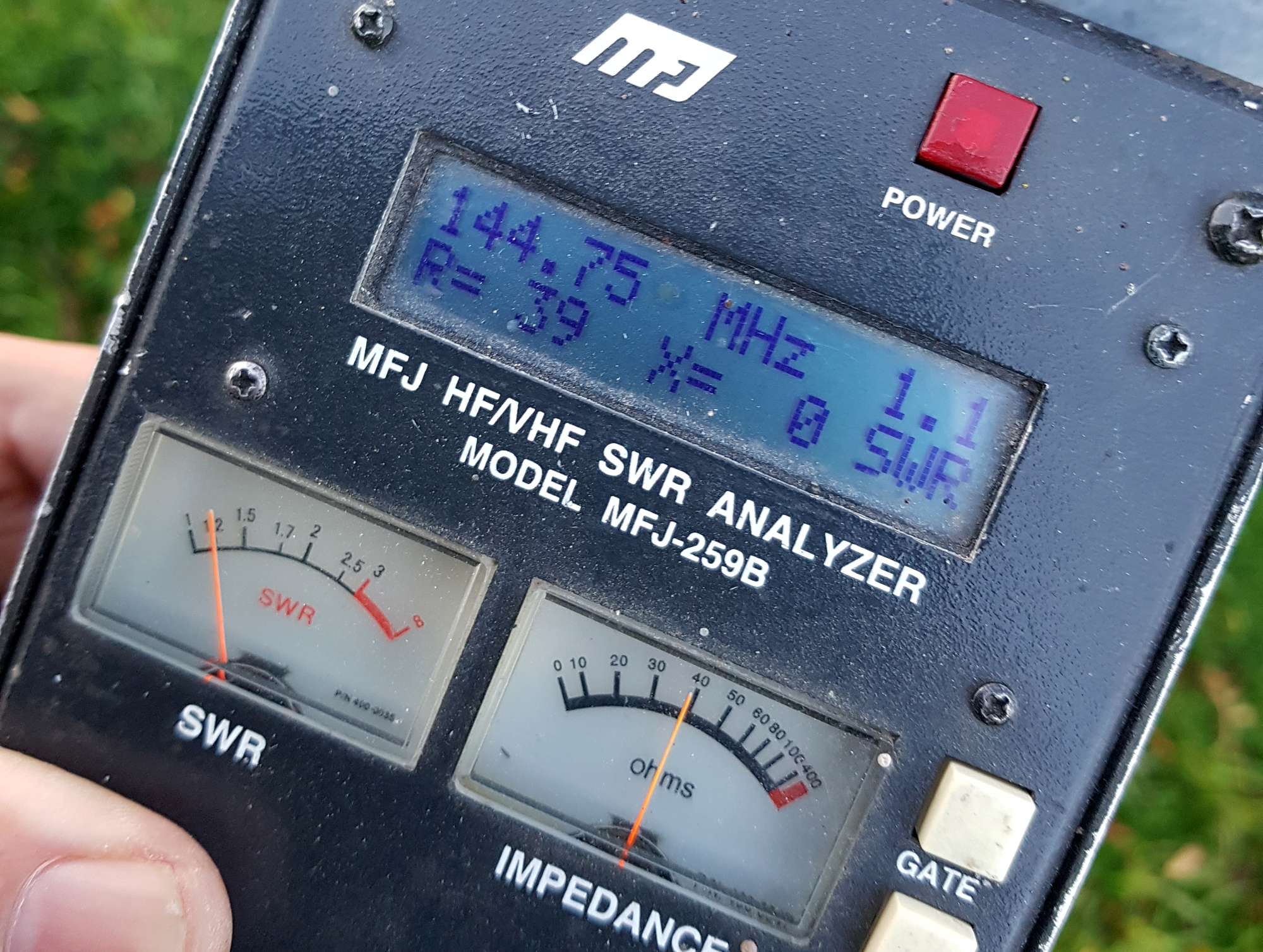
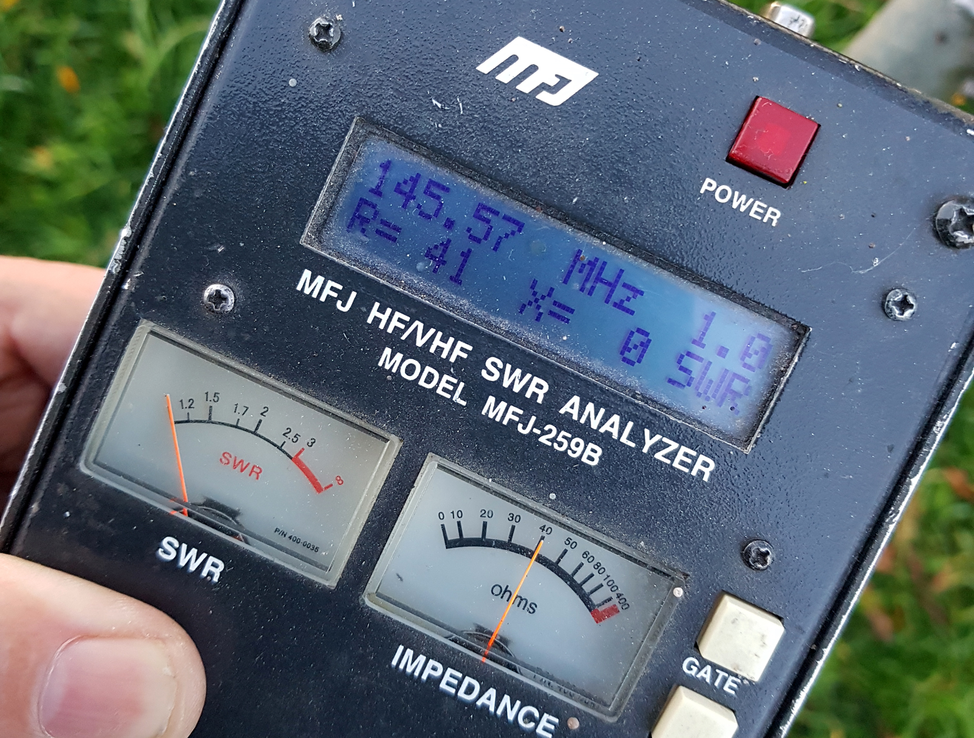
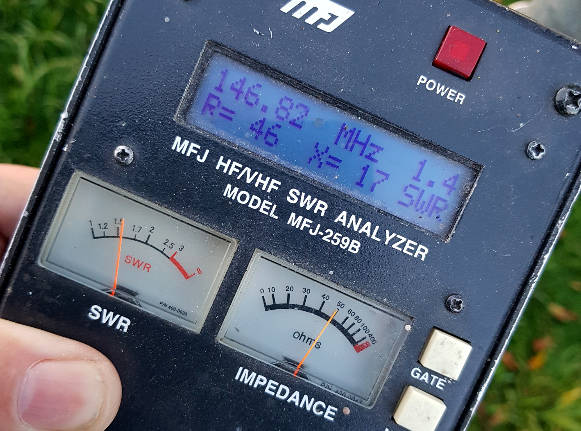
If you so wish, there’s nothing to stop you using this as a ‘horizontal’ antenna. The choice is yours – as with most OWA antennas, it’s very wide-banded and covers 144-146Mhz with ease. Here’s a few images to give you an idea of the antenna’s operating bandwidth.
All antenna dimensions are in the EZNEC file here.
As of January 1st 2022, Roy Lewallen [W7EL] has made ‘EZNEC’ a FREE application.
Download the core product here to view the file and all dimensions and antenna data.
Enjoy your build…
73 – Steve G0UIH Q82.uk

