
A 20/17/15m 10 Element Tri-band Yagi
UPDATED: March 2026
Back in 2020 after I’d retired, when conditions on the bands weren’t that good to say the least, I was asked by a UK Amateur friend if I would mind modelling something for 20/17 and 15m that was [quote] “Something like the Optibeam OB10-3W” – but not the same price range, but was within an acceptable reach of the homebrewer. “Can I build my own cheap version” he asked.
The ‘Optibeam OB10-3W’ is 3 full size elements on 20m, 3 on 17 and 4 on 15m. It sports a single feedline into a 2:1 ferrite current balun and has very respectable forward gain and front to back figures on all 3-bands. It’s a quality, albeit pretty expensive antenna at around £1670.00 GBP from ML & Son and around $2350 from DX Engineering. Prices quoted are correct as of March 2026 when this article was updated.
A friend of mine originally owned a OB10-3W about 10 years ago but unfortunately he’s now SK and the manual seems to be lacking online; so, following some modelling I came up with an alternative design of my own.
But before you look to go down this route, there’s a couple of things to know first. I didn’t spend a huge amount of time honing this antenna. It’s bit [raw] and rough around the edges as they say and is certainly open to improvements.
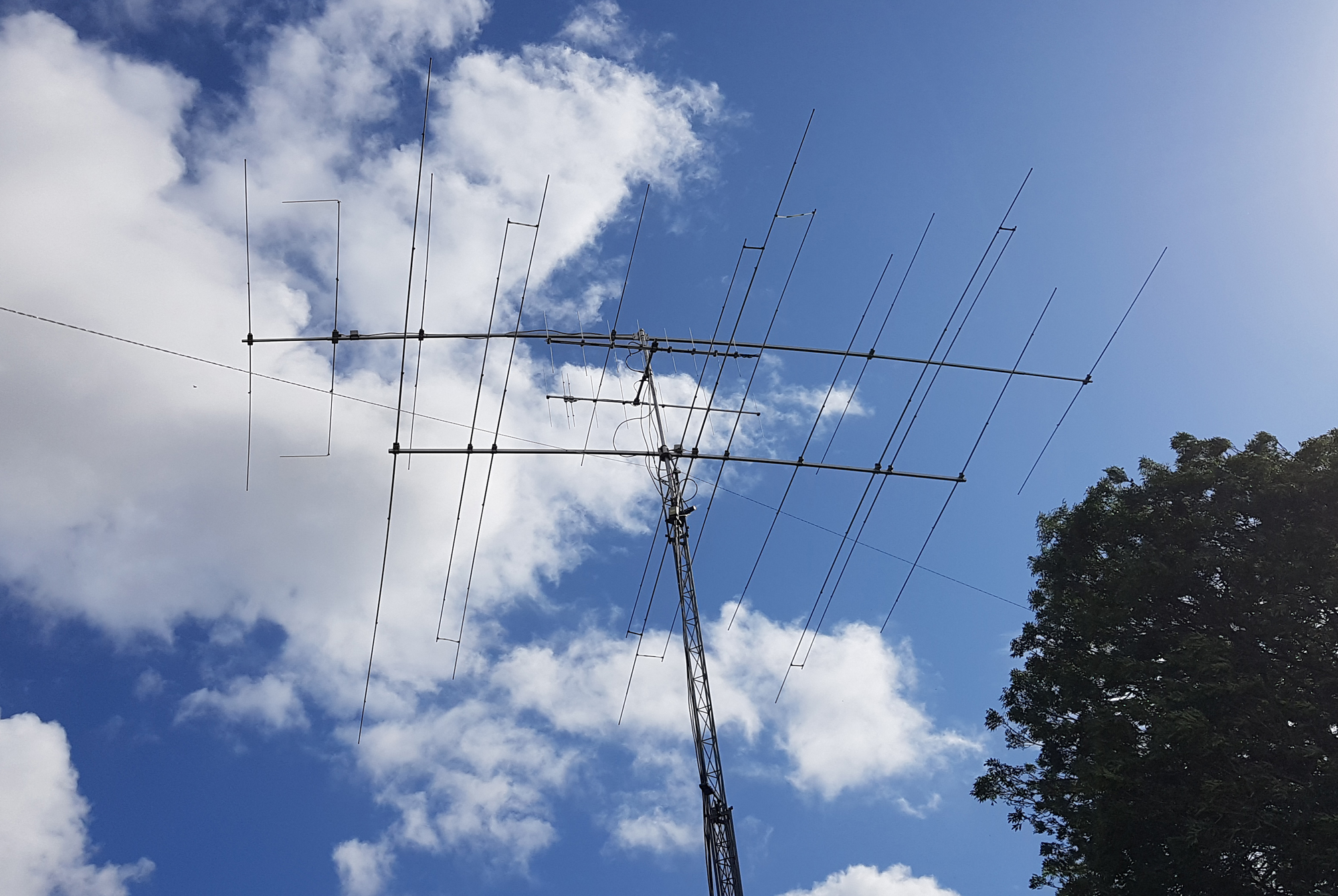
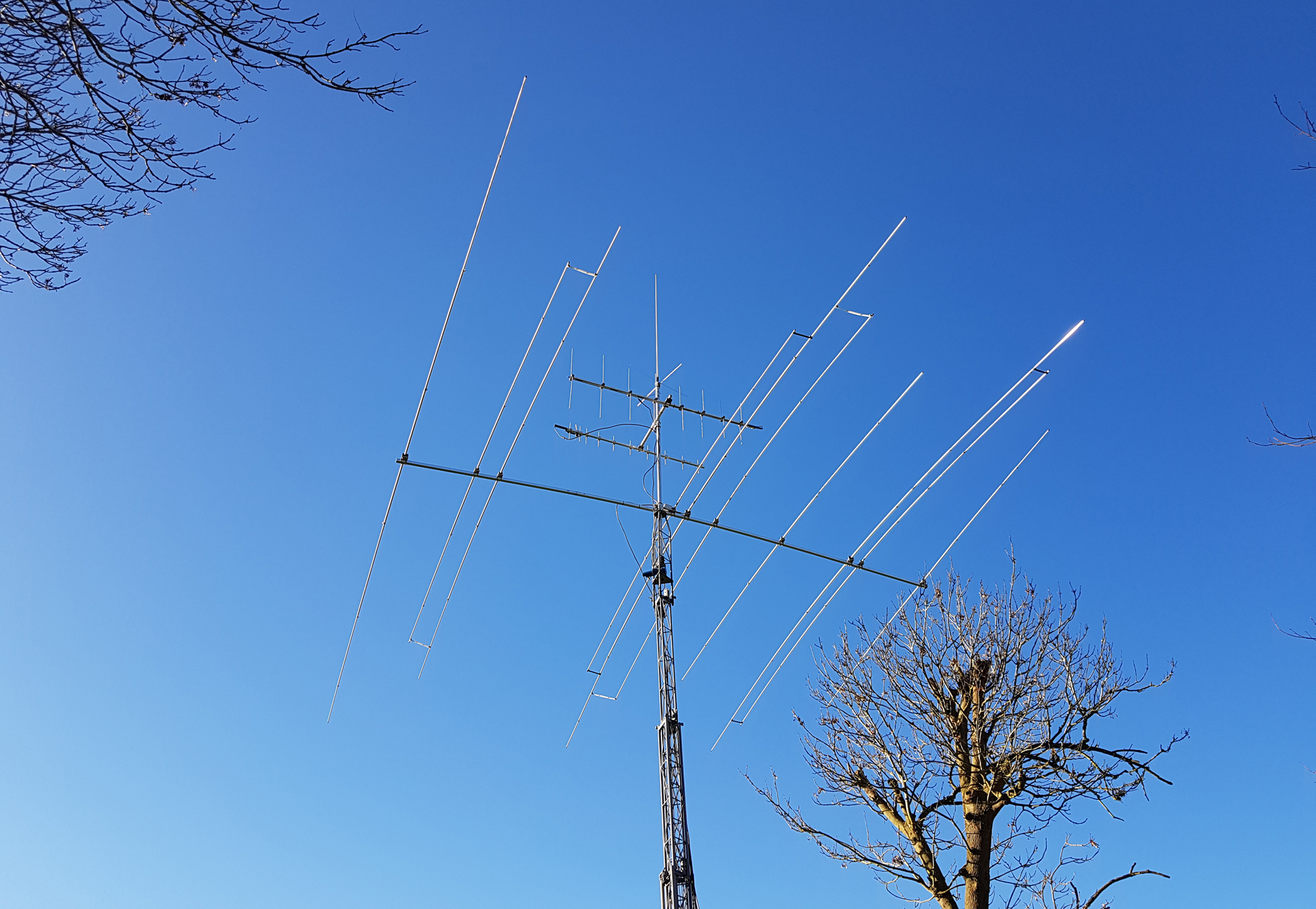
Saying that, I originally decided to model it, but as time went by, I actually ended up building the real thing as I had no real good 20/17/15 m solution. 10m wasn’t needed as I’ve a good big 6 element monobander in that part of the spectrum, but following construction, I still continue to use this cheaper homebrew version as my main 20/17 and 15m antenna with great results.
An initial model was put into EZNEC and I came up with a design that had very similar figures to the ‘Optibeam’ version, albeit on a slightly longer boom. Saying that, the impedance is closer to 50 ohms so you can use it with any 1:1 current balun using either a ferrite or a cheap air-core homebrew version using coiled coax, so you’re saving £100 from the word go rather than using a fiddlier 2:1 transformer.
The antenna is fed via a single feedline which hooks up to the 20m driven element and is inductively coupled to the 17 and 15m elements.
After various modelling and changing some parameters [especially element spacing in some areas], I ended up with a nice design with some figures that showed a fairly stable antenna.
Here’s the outcome:
For ref, both versions of the antenna are 3 full size elements on 20m, 3 full size on 17m and 4 full size on 15m, so you’ve monoband performance on all 3 bands.
I found my ‘homebrew’ design wasn’t too critical. SWR on all bands was good, although 15m was a little ‘peaky’ at the band edges. Actually, the SWR on 15m is a little low in the band, resonating around 21.175Mhz so it could do with a minor tweak – but nothing really to worry about.
Saying that, 20m never exceeded 1.2 to 1 across the whole 350khz of bandwidth and 17m was dead flat indicating it was a fairly low Q design. Front to back seemed good on all bands and on 17m an S9+20 signal was reduced to S8.5 indicating around 23db. On 20m a 5/9 signal was reduced to 5/5 when rotating the beam 180 degrees indicating over 25db and on 15m an S6 signal became nearly unreadable indicating rejection approaching 30db.
Forward gain in modelling gave figures very similar to what Optibeam quote and on-air, the antenna seemed very potent. I managed to work E51WEG [easily] in the South Cook Islands on 17m FT8 using only 10w with a report of +5db – so it’s working very well.
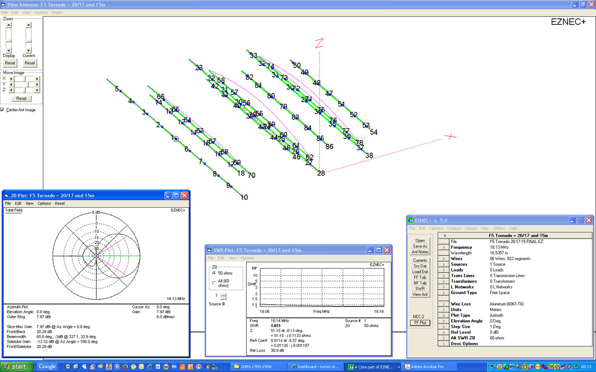
Click on the image for a hi-res PDF
Unfortunately, when trying to compare, Optibeam quote some very oddball gain figures. The standard of quoting ‘Freespace’ dBi which is an industry recognised method – is not used. They do however quote a dBi figure based on an antenna height of 20m above ground. Seems to me a bit of a smoke and mirrors approach and not sure why this is. Saying that, forward gain on 20m is around 7.5dbi, on 17m is around 8dbi in freespace and around 9dbi on 15m.
So, onto the build. I calculated the required number of aluminium tubes required, and based on a homebrew purchase, I estimate the maximum outlay for tubes/boom from a metal supplier would be no more than £375. Add some stainless hardware, a few element mounting plates and some pseudo cheaper ‘Stauff’ type clamps and I’d be surprised if your total budget went over the £500 mark. Pretty reasonable for an antenna of this calibre.
March 2026 Update:
There’s two ways of approaching this project. You can either download the .EZNEC file [link at the bottom of the page] and follow the lengths directly. Dimensions have been updated which reflects using 30, 25, 20, 16 and 12mm tubes for the 20m elements – making it heavier duty. There are also minor updates to the 17 and 15m element lengths. In particular, 15m was quite ‘peaky’ at both lower and upper frequencies. It’s been improved but still picks up quite rapidly – especially at the high end above 21.400Mhz.
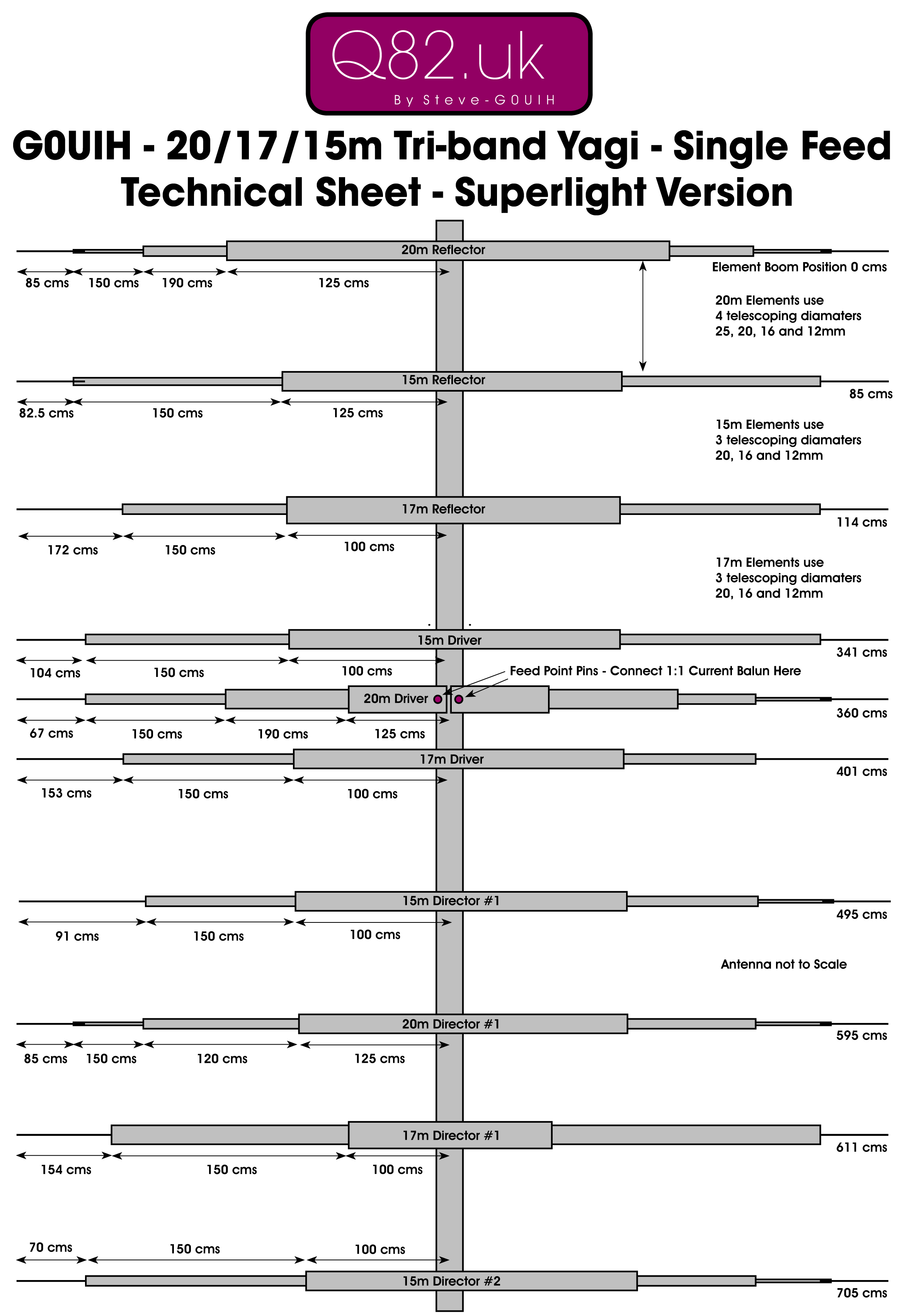
Optionally, you can follow my own build data below for the ‘Superlight’ version. I went this route as I already had 25, 20, 16 and 12mm tubes in the workshop. This build uses only 4 sizes of tube on the 20m elements. The EZNEC version uses 5.
Enclosed below is the plan and by clicking on it gives you a hi-res PDF with all the measurements. Follow this exactly and you’ll find it works from the start.
For a 1:1 balun, you can use either a ferrite core current balun. You can construct one here if you like, or for the budget version, coil 11 turns of good quality coax [not RG58!!] around a 4.25” air former as per G3TXQ’s info here. He used RG213 which should handle some power and is relatively cheap.
Place the choke or balun immediately at the feed point of the antenna and this will help keep unwanted RF currents off the outer braid of the feed line. As a final touch, I cut some plastic strips to act as ‘spacers‘ between some of the closer spaced elements. When it was windy weather, I noticed the SWR would move [not a lot] but move it did – when the wind blew. The spacers now keep the element spacing constant with no variations.
I’ve not included any modelling files as TBH, this antenna just works great as it is. OK, the boom is a little longer than the Optibeam version, but you don’t have to bother about a 2:1 balun which saves £100 from the start, and performance wise, it works great as it is without any fuss.
Below is the positioning for all the elements on the boom. Clicking on it gives you a hi-res PDF with all the measurements.
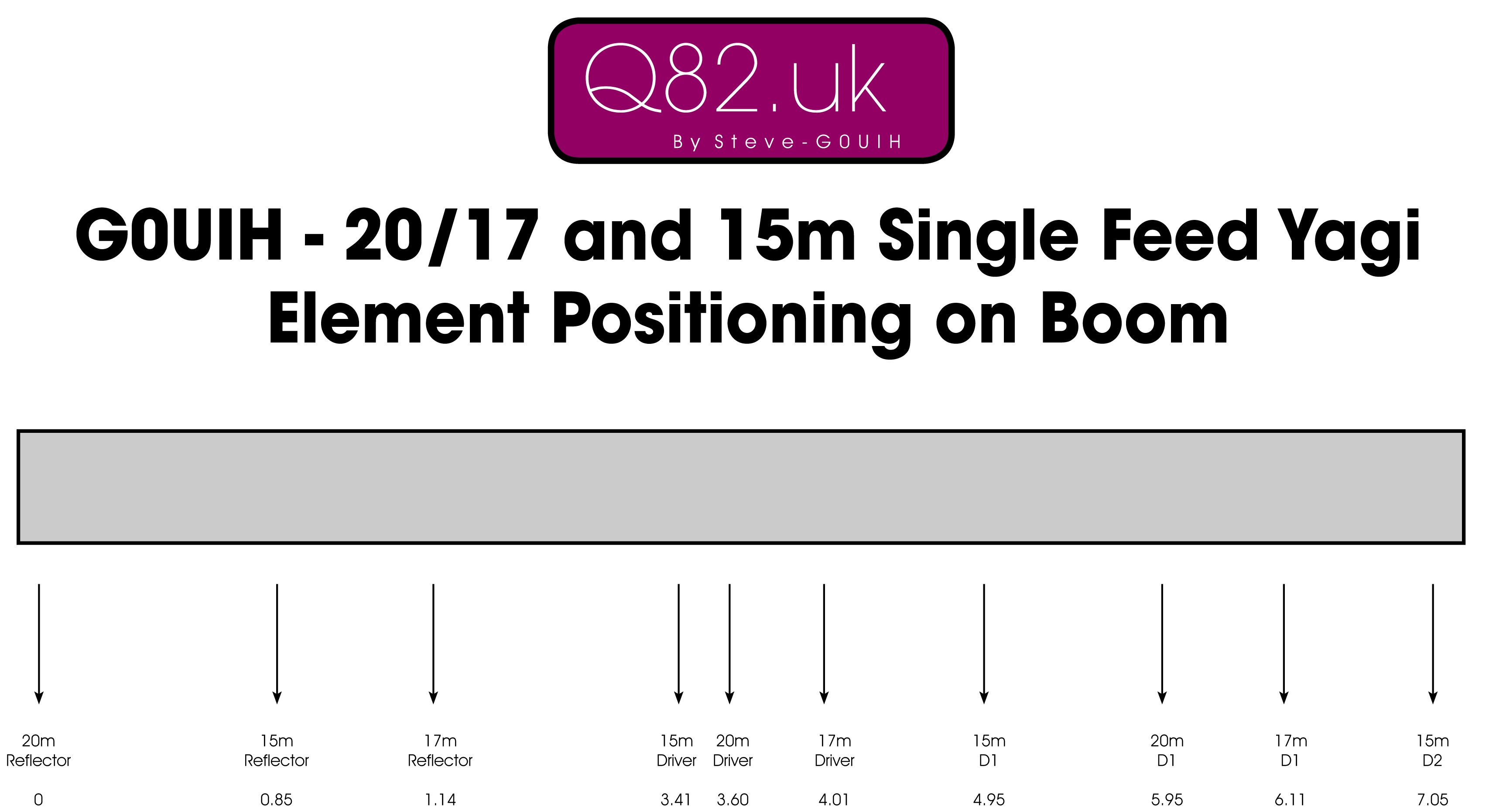
The dimensions are based on a real-world build mounted on the tower at around 50 feet. A 10m 6 element OWA mono-bander mounted at 10 feet above made no difference in the way the tri-bander performed or on the SWR curves on any band.
We also checked it with the 10m antenna removed – there was little change.
It’s just a winner – and a cheap one at that making a great 20/17/15m solution for the homebrew enthusiast. If you decide to build it – let me know how you get on.
Here’s the new March 2026 V2 EZNEC file for your reference.
If you don’t have EZNEC, download EZNEC Pro/2 here from the W7EL site
Good luck with your build as always.
73 – Steve G0UIH
Q82.uk

