
Build a 2 Element 15m Delta Loop
Here’s a super project for 15m aficionados. It’s a great 2 element Delta Loop for the 15m [21Mhz] band with a boom length of just over 2m and makes for a great compact solution. It also makes a very good alternative to a Yagi.
Here’s’ some of the antennas excellent selling points!
* Will outperform an equivalent 3 element Yagi
* Has a boom length of just over 2m. A 3 element Yagi has a boom of over 5m
* Wideband – covers the whole band at under 1.6:1 SWR
* Actual ‘real electrical’ antenna height is 2/3rds of the way up the vertical legs.
* At 19 feet ‘boom height’ it will perform equally or better than an equivalent Yagi at 25 feet
* Super low-noise ‘Closed Loop’ design – far quieter than any Yagi
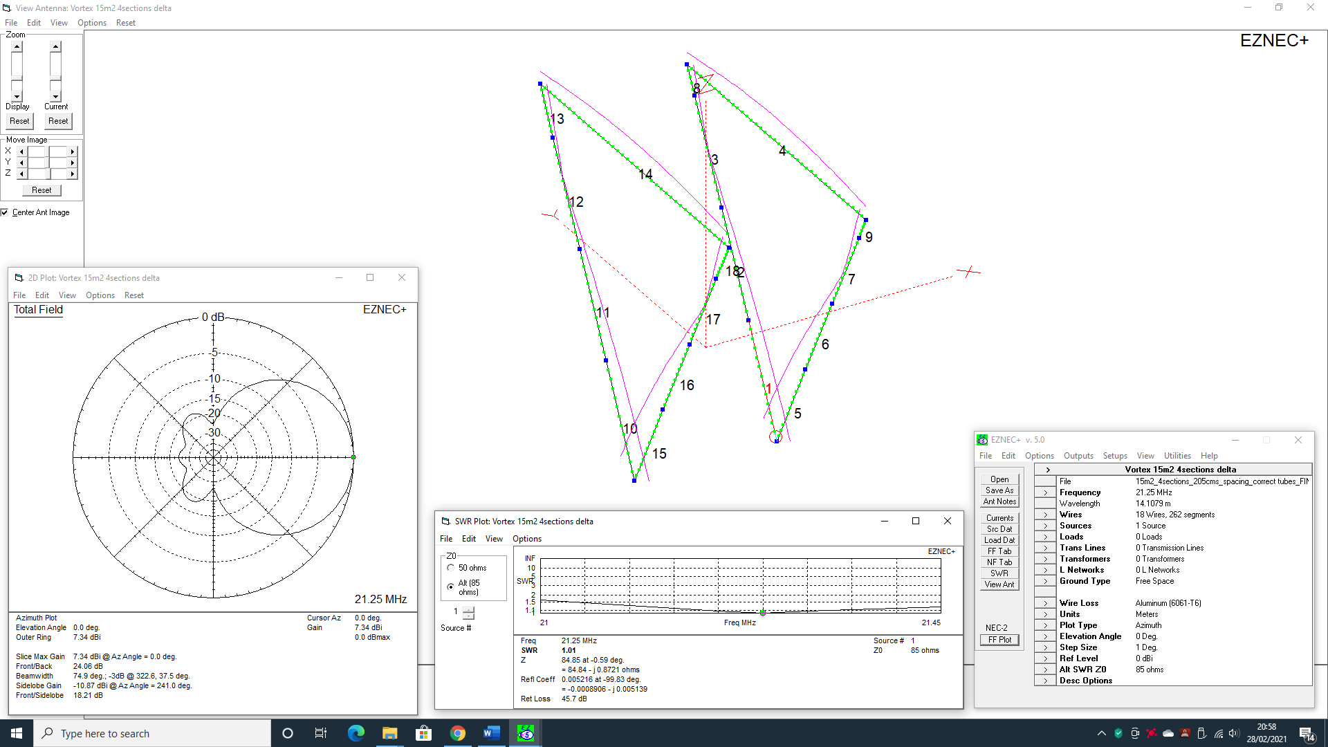
* No point modelling it – just follow our info sheet below [we’ve done the hard work!]
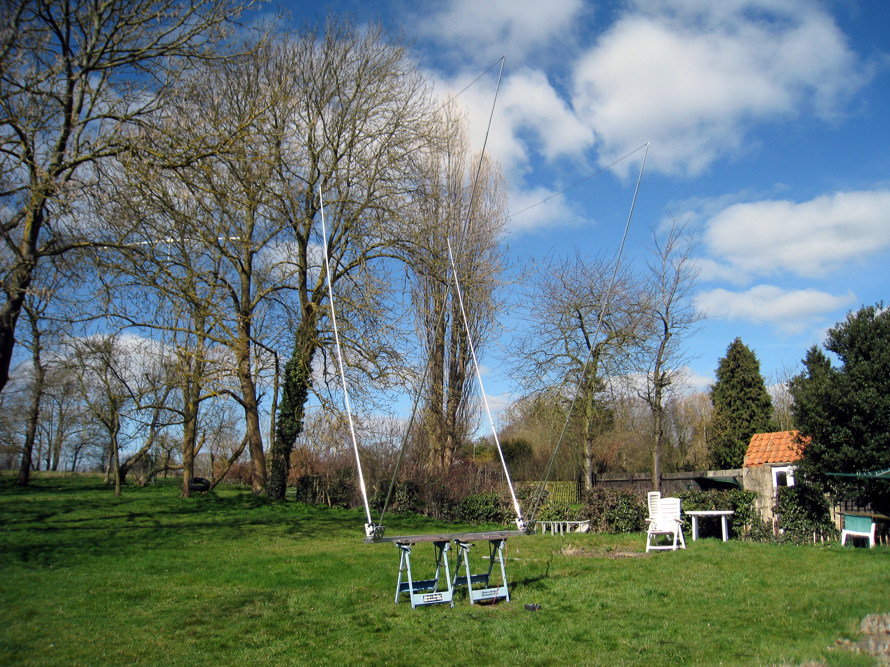
So – you fancy building one? – Here’s the info on the element tubes and all the data required to get you up and running. If you need a hard copy, click on the image below to download a PDF. Data on the gamma match, tube and settings are also included further down the page.
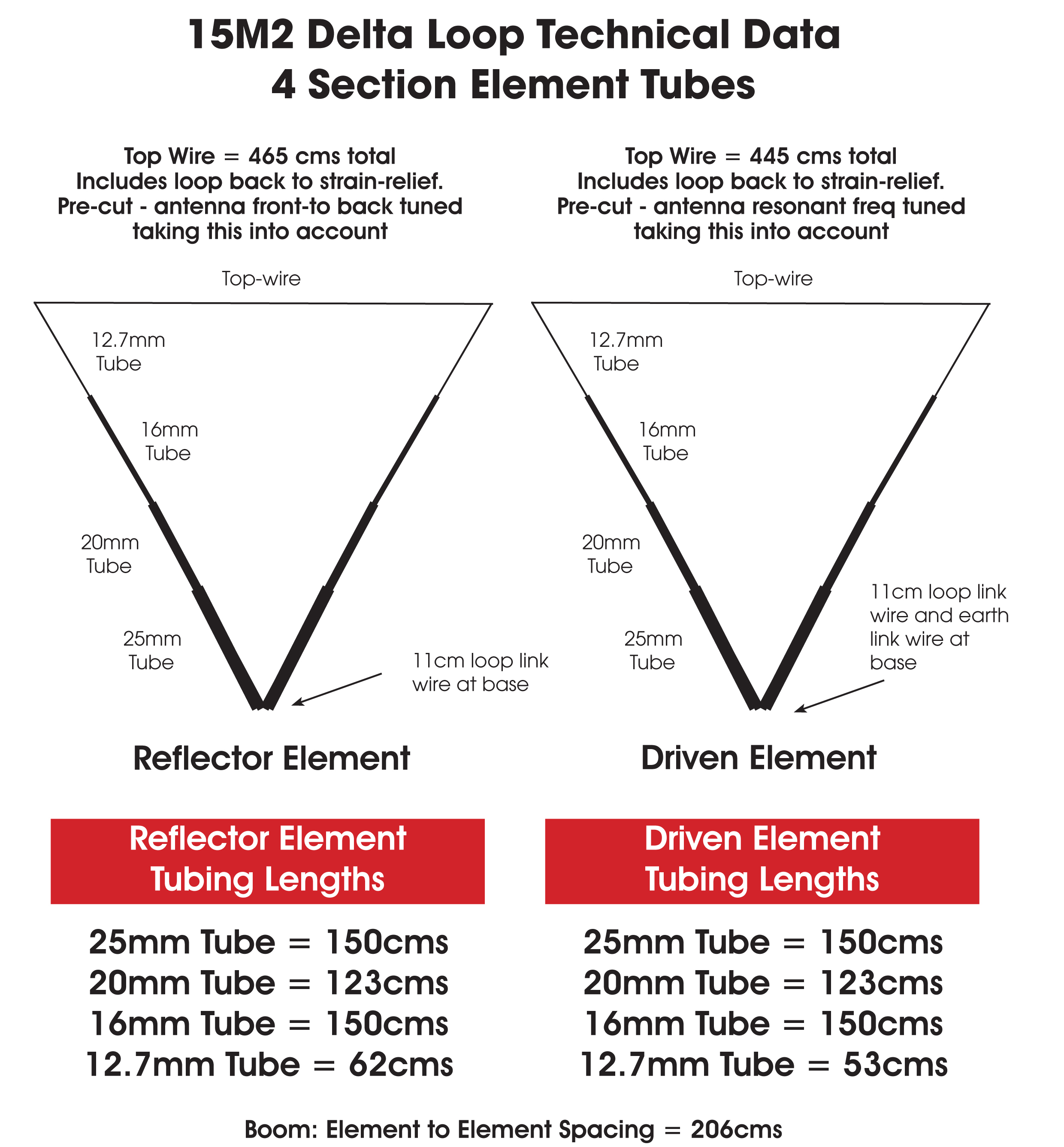
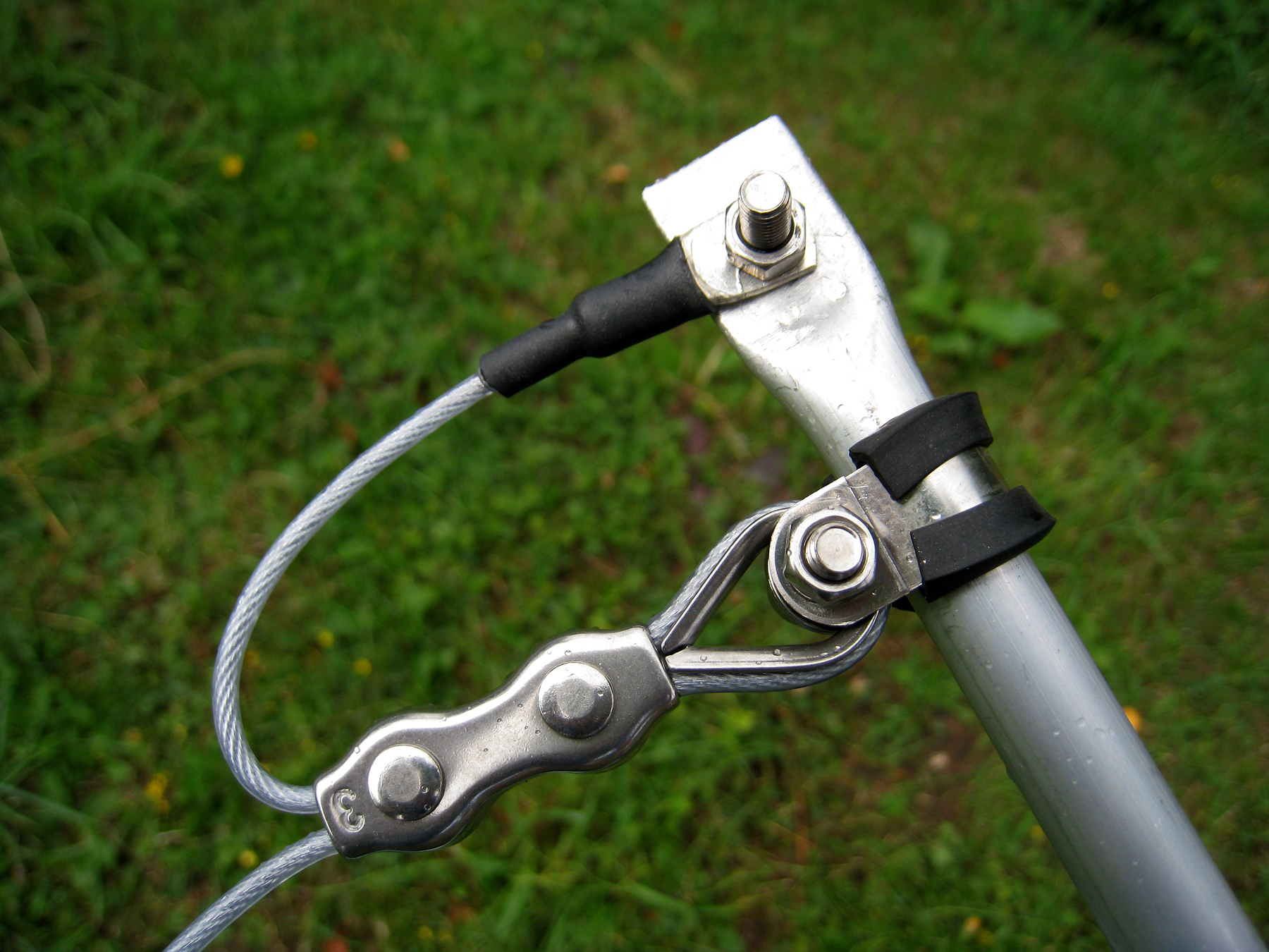
See the image below on the ‘Strain Relief‘ mechanism as you actually make the top-wire slightly longer to accommodate a ‘Tie-Back‘ scenario. For example, a ‘full length‘ top-wire is looped back approx. 17cms on BOTH ends. Therefore, a top wire of 465 cms in total, loops back to 431cms [i.e. 465 -17 -17]. These lengths have been used in the ‘Real-world’. Our ‘Rule-of-thumb‘ is 17cms on each loop back [34 in total] for each wire.
Reflector Top Wire:
We used a 2mm ‘Polyweave‘ style of wire for the reflector top-wire which is PVC coated. It’s very very strong with 7×7 strands of steel wire [you can also solder it!] – but untrue to what the data shows, it can’t handle huge amounts of RF power. We’ve tried it and above 1kw it’s toast! Using this wire for ‘Parasitic’ elements is ideal as these elements carry no RF current. It’s also cheaper than ‘Flexweave’. Using bare wire is not recommended as the velocity factor of the wire is different. The PVC coating changes the v/f of the wire and as such, the lengths shown here will not be correct.
Driven Element Top Wire:
We used a 14 AWG ‘Flexweave‘ style of stranded copper wire for the driven element top-wire which is PVC coated. The total diameter including the PVC is about 4mm. It’s very strong but easily handles QRO. Using this wire for the ‘Driven Element’ is ideal as it is very capable of 2kw+. Using bare wire is not recommended as the velocity factor of the wire is different. The PVC coating changes the v/f of the wire and as such, the lengths shown here will not be correct.
The additional top-wire lengths have been compensated for in the actual build. We’ve checked each loop for the correct resonance within the model. What you see here is correct.
The top wire is looped back over the thimble by approx. 8.5cms and then by another 8.5cms to the connection on the tube.
Using this method takes the strain totally off the top wire. No more broken top-wire connectors.
GAMMA MATCH INFO: Download the Gamma Match data here
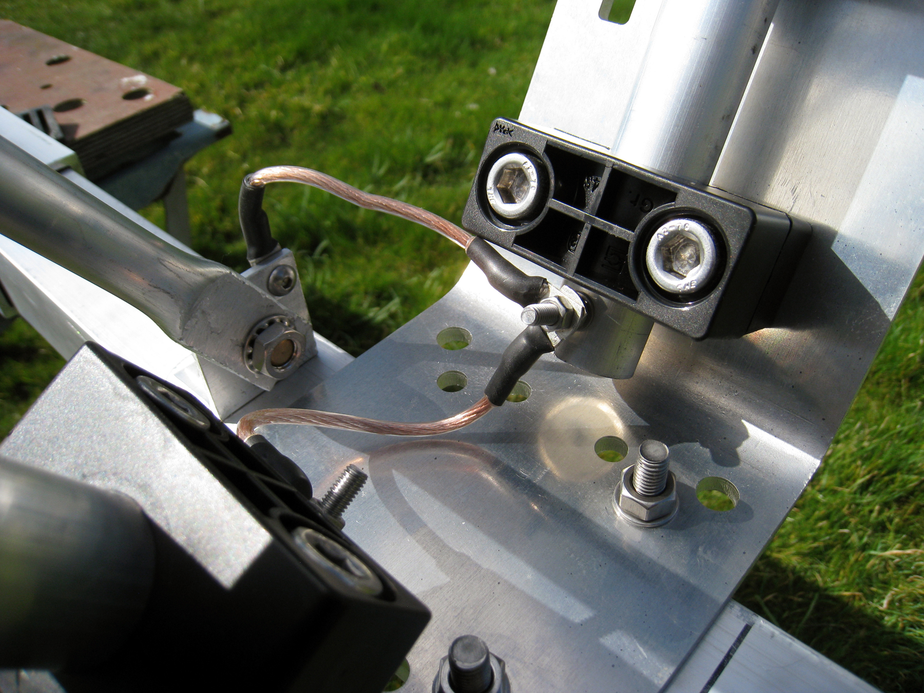
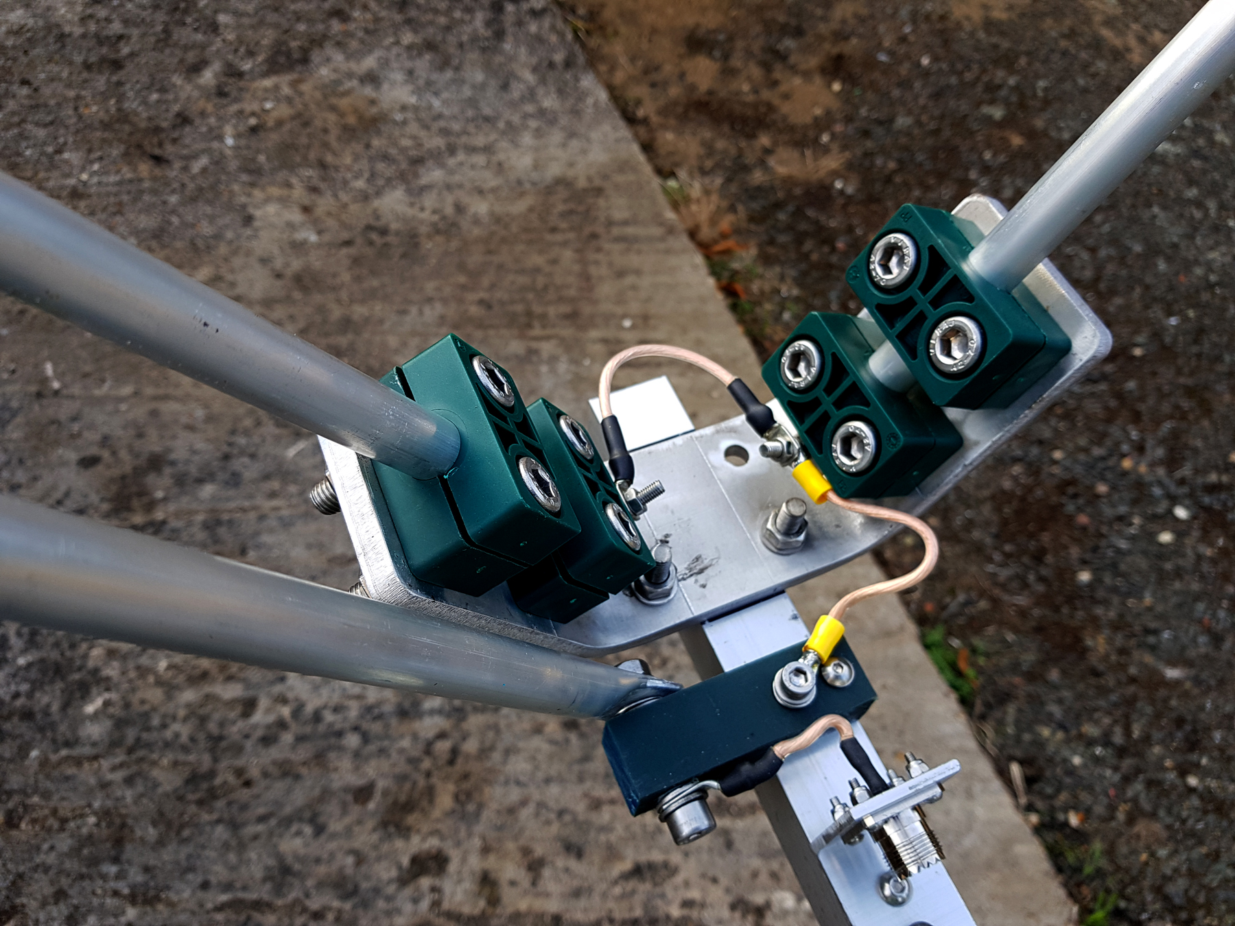
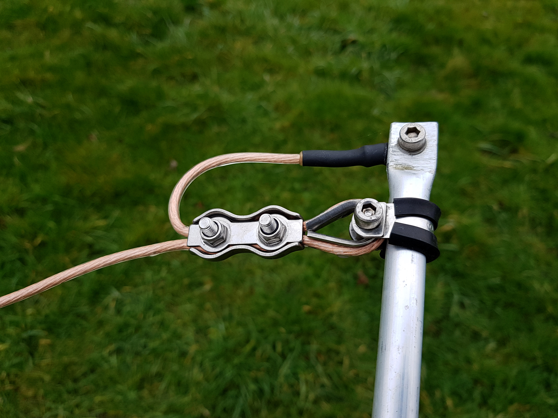
Here’s an update to the driven element. Instead of using a ‘threaded’ 3/8th inch stud to mount the gamma match, we use an M8 bolt which is mounted to a separate nylon mounting section. The bolt sits in a 12.5mm PTFE insert so handles very high power as ‘QRO’ can melt nylon. A small length of ‘Flexweave‘ then goes back to the rear of the SO239 socket.
I found a good supplier of quality SO239 sockets which has PTFE insulation. Check out Barenco’s site here. This enables us to use an external higher quality SO239 [or any other good quality coax socket].
The M6 socket [Allen] cap head bolt with the yellow soldered crimp connector is the earth and is connected to boom/chassis earth. This subsequently links to main element tube. This gives a great result all-round.
Have you built one? – if so, let us know and we’ll let the community know on how you got on with your build.

