
An XLR Balanced Audio Switch Box
Here’s a nice shack project for those who run a balanced audio set up. The box allows for a single XLR Balanced input and then two user selectable outputs – either ‘A’ or ‘B’. This would then allow the user to have a microphone on the input and have a choice of selectable outputs.
The outputs could be anything that suits. For instance, Output ‘A’ could go direct to the radio and output ‘B’ could go to an audio rack/EQ and the like – so giving you two separate tailored audio solutions.
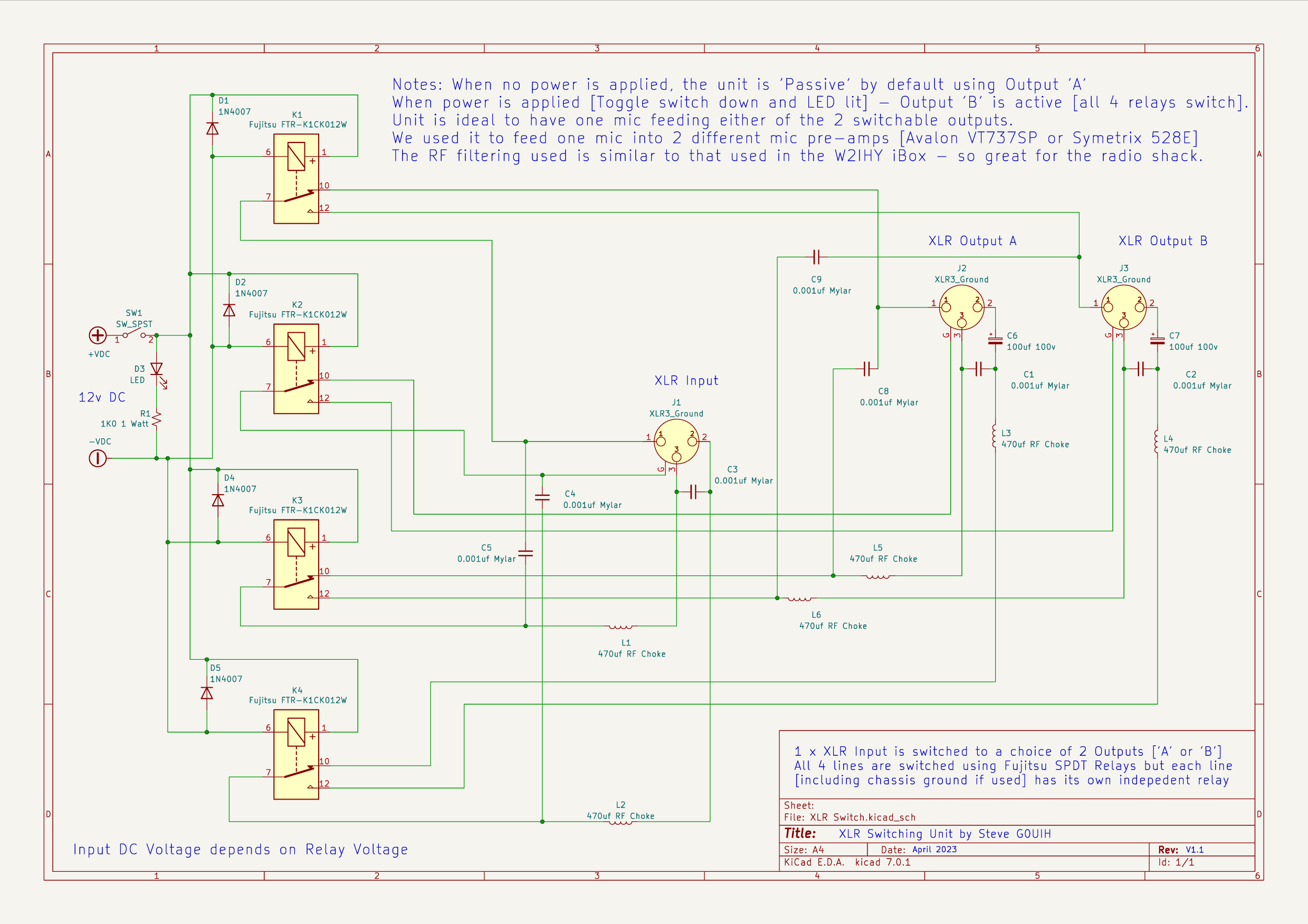
Switching is achieved using FTR-K1 Fujitsu SPDT 12v relays and using 1 relay per switching line gives excellent isolation. All 3 lines from the XLR connector are switched plus the 4th [optional] chassis ground, although not everyone uses this 4th connection.
The box also has a good RF filtering circuit using a similar setup [but slightly cut-down circuit] to that used in W2IHY’s iBox, but minus the transformer. We’ll have another project where you can build a similar unit to the iBox [complete with transformer] at a later date.
The actual build will commence in the Spring so you can follow the progress here on Q82.uk
Schematic update to V1.1 – April 1st 2023
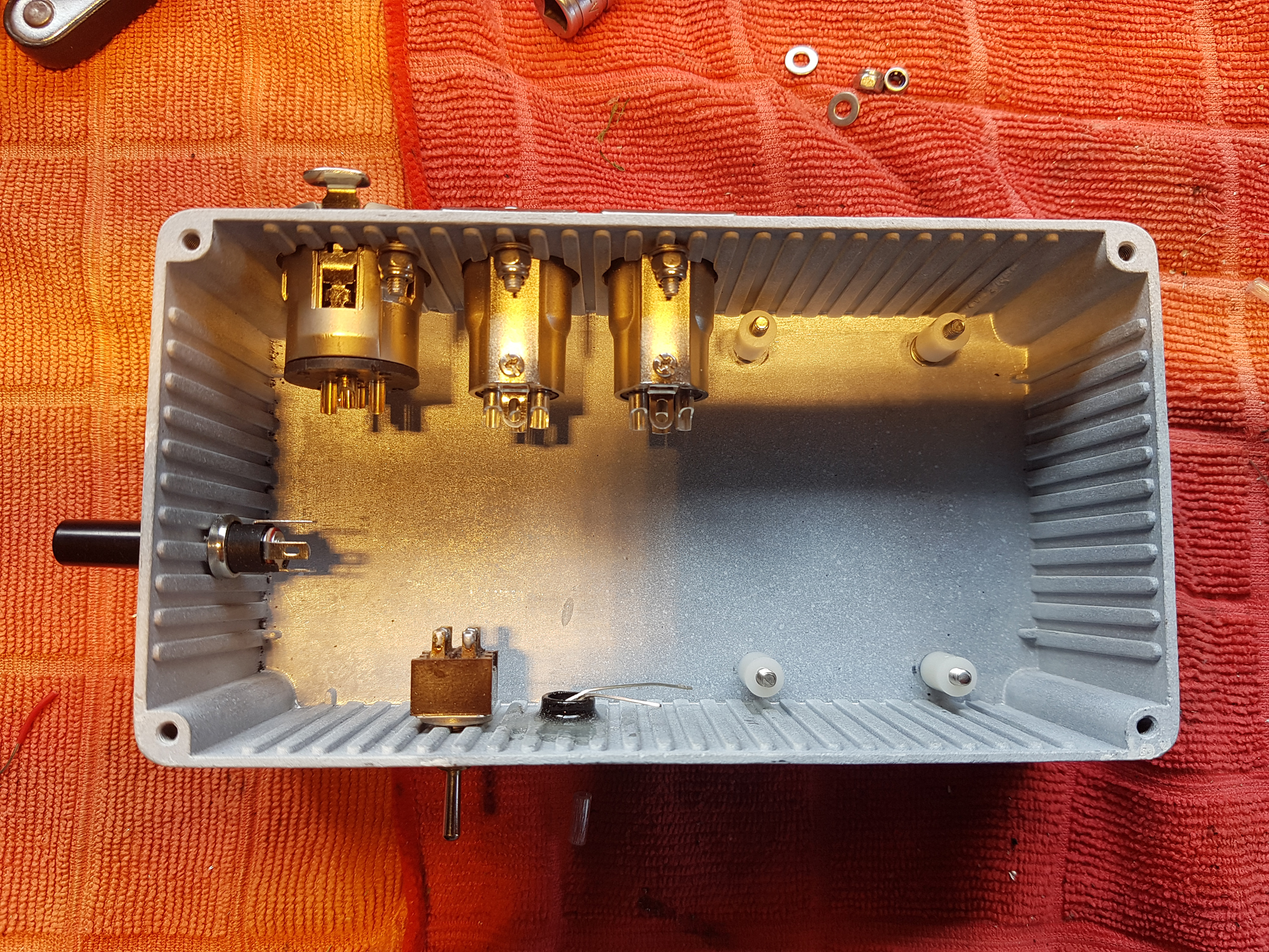
Update: April 2023: I’ve managed to start the build and whilst searching for a suitable enclosure, I managed to get a £25.00 ‘Farnell’ enclosure [new] from eBay for a fiver [It’s advertised as being RF shielded [a bonus] – so that’s a result. Using the pillar drill, you can see the three XLR sockets used. Two are ‘Amphenol’ [New Old Stock from eBay] and one is a ‘Switchcraft’ – so both premium manufacturers. There’s a small toggle switch, an LED and a DC power input plug and socket. The base of the enclosure is also drilled up with some small insulators ready to mount the Veroboard homebrew PCB.
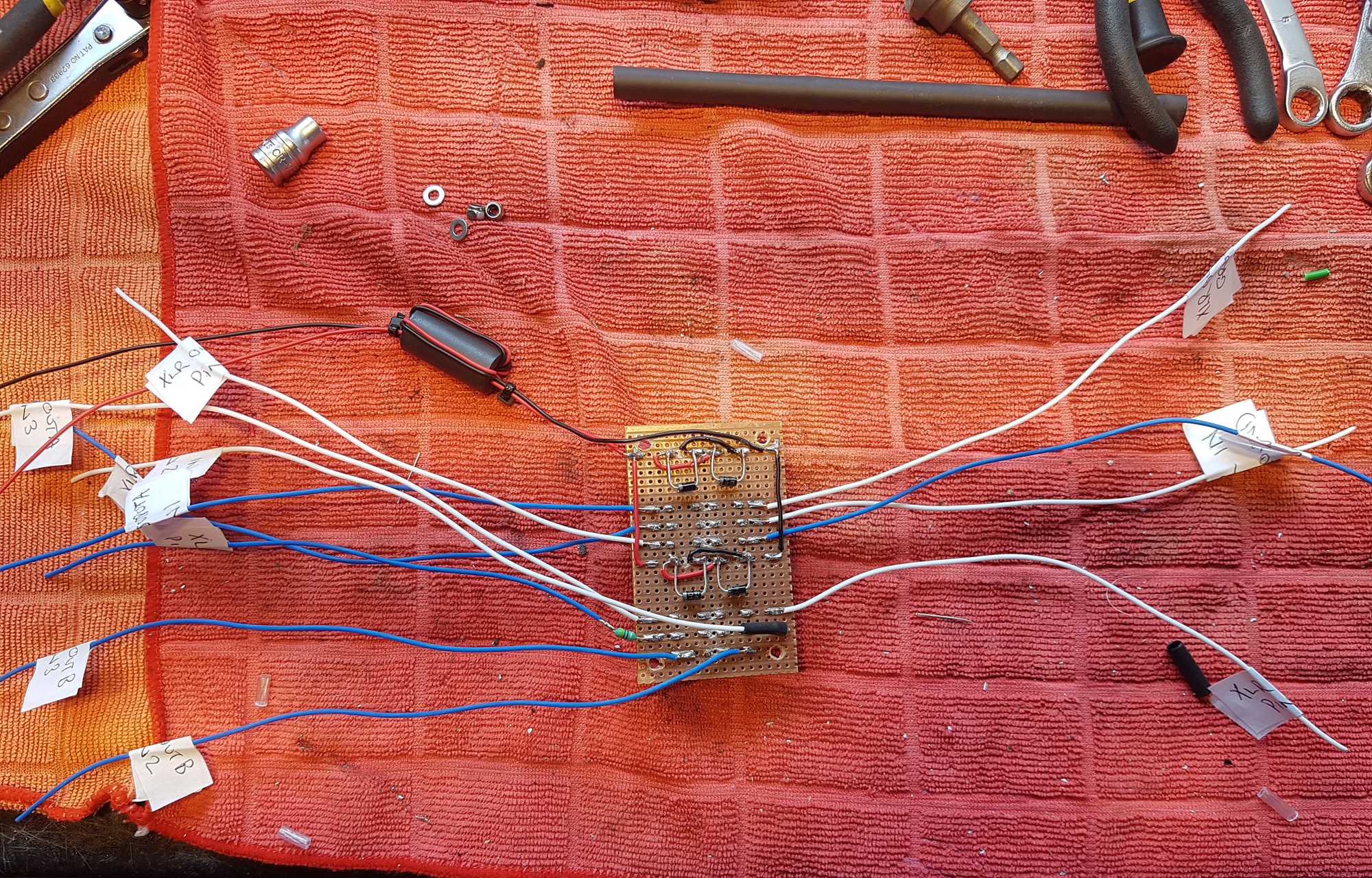
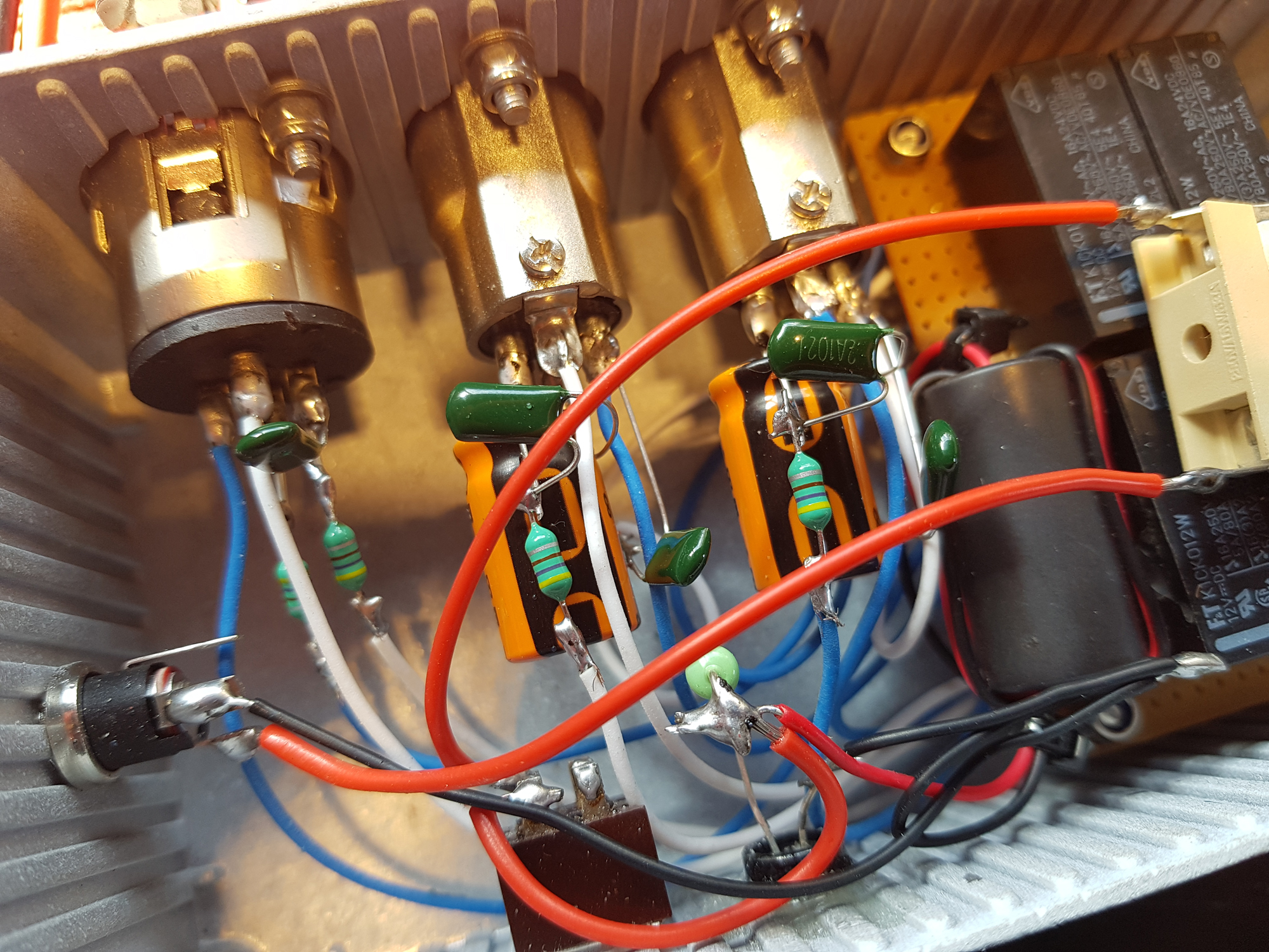
Here’s the PCB from a small piece of Veroboard. The 4 x FTR-K1 Fujitsu relays are mounted on the opposite side. 1N4007 ‘Flyback’ diodes are fitted to each relay and 2 small 470uf RF chokes can be seen. Saying that – the chokes were removed as they need to sit in a slightly different position and on the wires nearest the sockets.
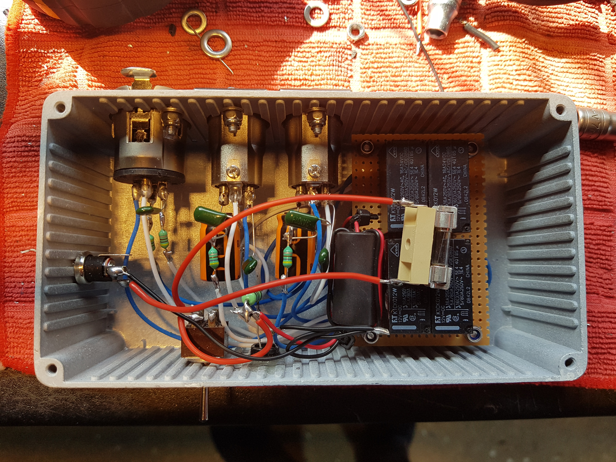
I’ve now had a chance to assemble everything and a ‘dry’ test prior to assembly confirmed all the switching worked as intended [always a bonus]. Remember, this isn’t just a single line switch. The relays switch all 4 lines. If the unit is not connected to a 12v supply [or is turned off], then Output ‘A’ is ‘On’ by default and can used as a passive switch. If you switch on the power, then Outputs ‘A‘ and ‘B‘ can be fully switched as required.
So – next job is to finish the assembly and a tidy up. Then it’s a test in the shack.
More on how she works out later.
Schematic has been created using KiCAD V7 which is an open-source community driven program.

