
G7FEK Multiband Wire Antenna Suited for DX
Back in the late 80’s, G7FEK published a wire antenna design aimed at amateurs who have a limited amount of space. The design covers bands between 80 and 10m. Some bands are naturally resonant, others like 17, 12 and 10m do require the use of an ATU although impedances are not that super high. Most commercial ATU’s will handle these impedances without an issue.
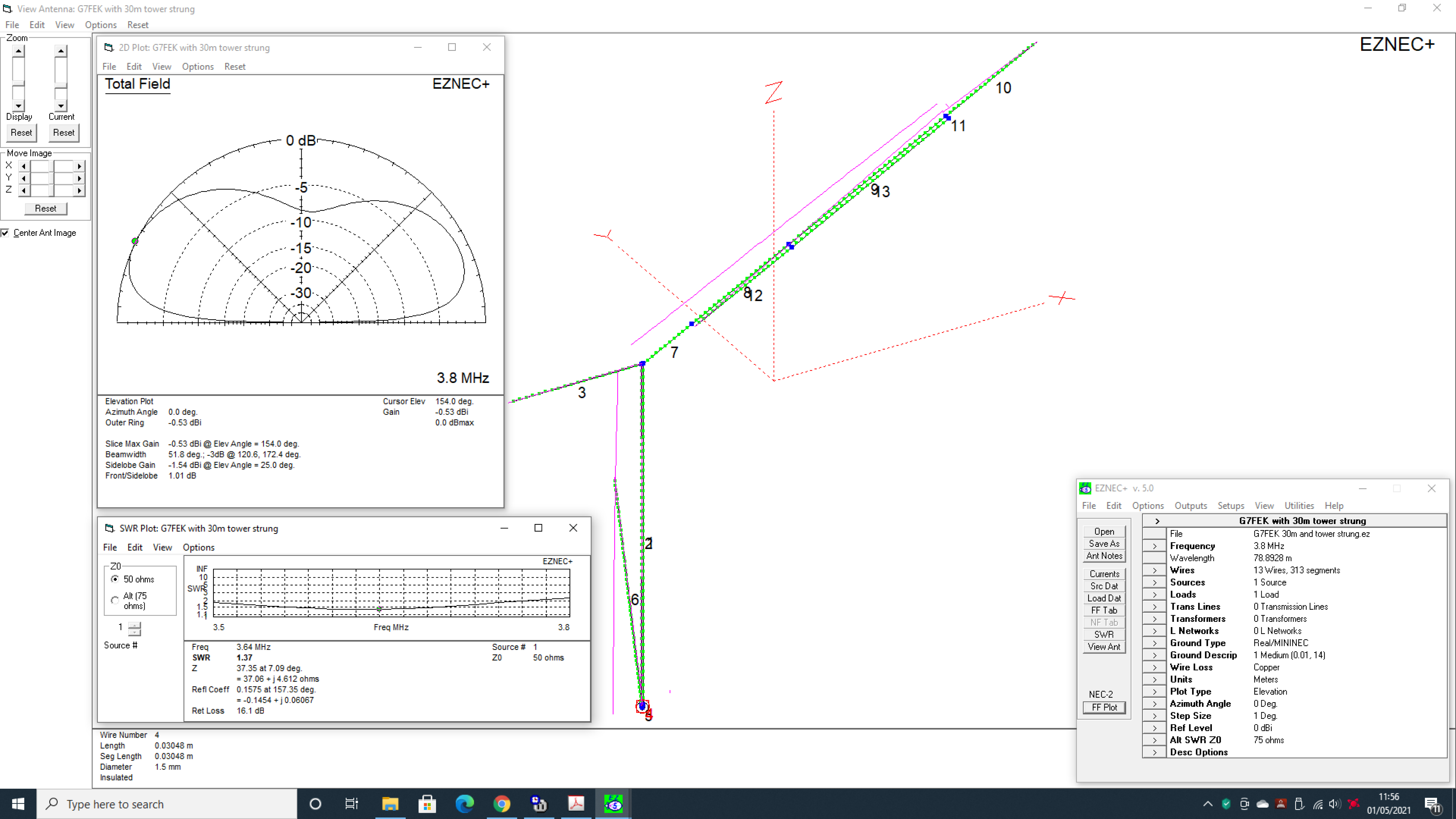
Looking at the model above, the top of the vertical section is only 7.5 above ground. The horizontal section then slowly rises to a maximum of only 11m – so this solution is possible for operators with the most demanding QTH’s. You can install this antenna on almost any house [although you may need a small vertical extension pole on a bungalow].
One bonus with the G7FEK antenna is that with most bands, the angle of radiation is low which favours DX. The slight downside is that it’s not a super high gain solution. Even so, and as an example, 80m gain is just under 0dbi but exhibits a nice low angle take off of only 26 degrees. On paper it promises to be a good solution for DX on 80. To get a full size dipole to give these low angles, it would have to be nearly a half-wave above ground [over 120 feet high] which is beyond the scope of most operators.
Other bands also favour low angle take off with 26 degrees also on 40m and 25 degrees on 30m. The added 20m section gives a slightly higher take-off at around 40 degrees but it’s still a useful DX antenna. On 17m the angle remains low at 17 degrees however on 15m the angle rises above 40 degrees but will still make good DX contacts.
Here on Q82.uk, I’ve modelled a G7FEK antenna complete with a couple of mods which include an additional 20m vertical section and a 30m linear loaded section which comes off the main long radiator. After optimisation the user has nice SWR curves on 80, 40, 30, 20 and 15m and as such, the antenna can be used without any ATU. 17/12 and 10m do however require the use of an ATU. Internal ‘radio’ ATU’s don’t count here – external tuners only!
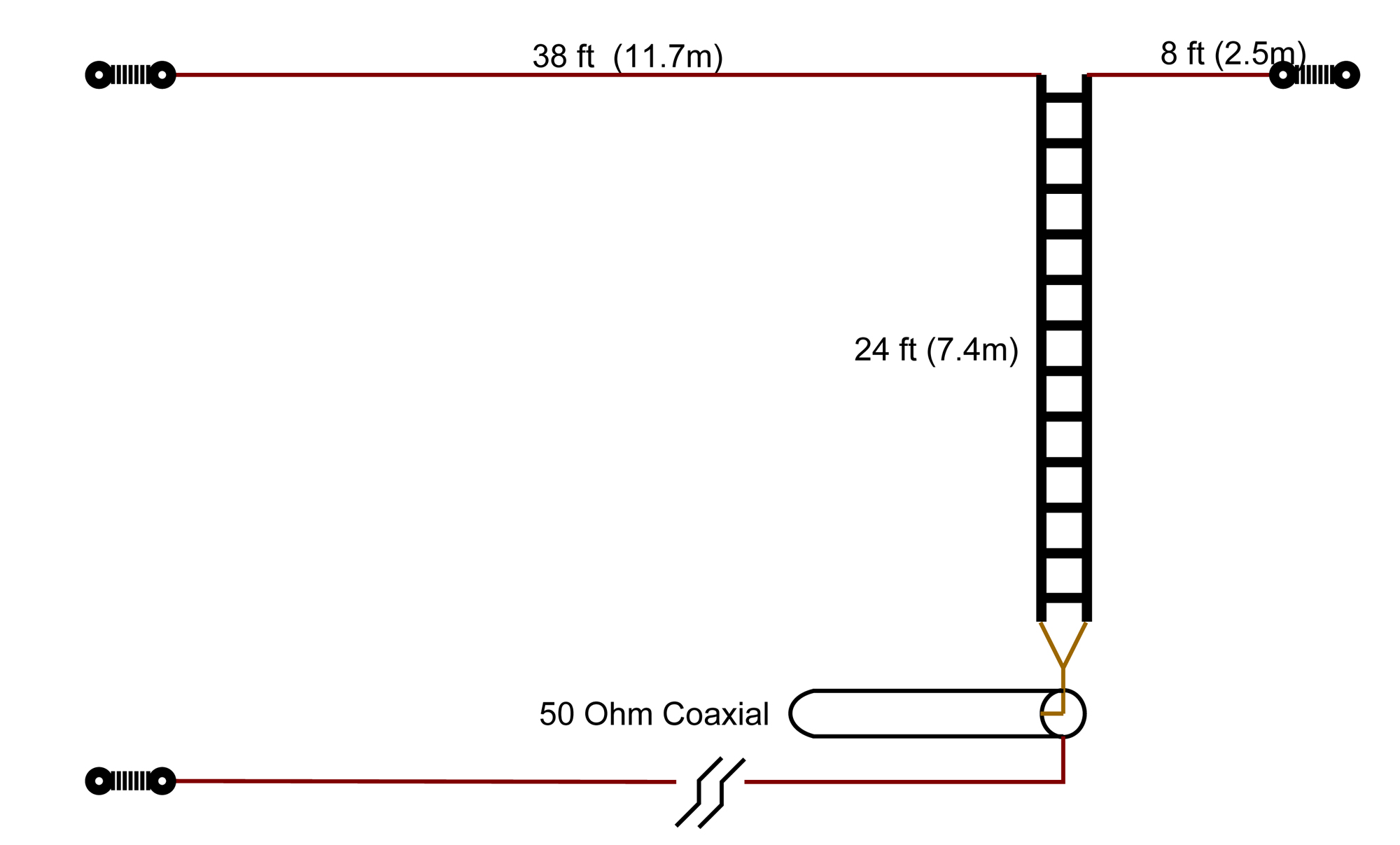
The enclosed EZNEC model has been modified and is based that the far end of the main wire is strung from a support such as a tower. The normal G7FEK model shows the antenna stretched out horizontally at just over 7m above ground level. We’ve tied the far end to our tower and have based it on a modest height of 12m. This would be similar to mounting it on the gable end of a typical house. by mounting the far end higher, has also added minor improvements in gain and has reduced the angle of radiation by a couple of degrees especially on the lower bands.
Download the latest info sheet from G7FEK’s website to give you the background on the antenna and how to construct one.
Download PDF’s of the Plots
Plots are based on a real-installation with a ‘Good Ground’ and NOT in free space.
G7FEK Antenna [Revised model updated by G0UIH] : 80m Plot
G7FEK Antenna [Revised model updated by G0UIH] : 40m Plot
G7FEK Antenna [Revised model updated by G0UIH] : 30m Plot
G7FEK Antenna [Revised model updated by G0UIH] : 20m Plot
G7FEK Antenna [Revised model updated by G0UIH] : 17m Plot
G7FEK Antenna [Revised model updated by G0UIH] : 15m Plot
G7FEK Antenna [Revised model updated by G0UIH] : 12m Plot
G7FEK Antenna [Revised model updated by G0UIH] : 10m Plot
Download EZNEC File
G7FEK Antenna EZNEC File [Revised modelling updated by G0UIH]
Notes: The EZNEC model includes a 20 ohm resistive load which emulates ground loss. EZNEC Pro/2 cannot model buried ground radials – only EZNEC Pro/4. Quote from the EZNEC User Manual about modelling ground [See pages 87 and 88].
“The third approach is to use MININEC-type ground, which models the ground reflection but not the conductive loss, and simply add a resistive load at the feed point to simulate the radial system loss resistance. The NEC radial model can be used in addition if desired. Approximations for the amount of resistance for a given number of radials can be found in Chapter 8 of The ARRL Antenna Book. (This reference gives total resistance for a quarter wave vertical, so subtract 36 from the values shown to use as the ground system resistance.)
Design: The G7FEK Antenna is an attributed design of Mike Dennis G7FEK

