
Match a Single Element Delta Loop
Matching a single element delta loop is quite a straightforward affair. The user has a couple of options. You can use a gamma match which is really a glorified capacitor to do the matching for you. However, you need to get the correct tube length and use an antenna analyser to get it set up correctly as the internal rod and shorting bar will need setting at the correct positions. Saying that, it’s a good all-round solution.
You can however make a slightly cheaper matching system by using a ¼ wave length of 75 ohm feeder from the feed point and then join it to any length of 50 ohm feeder which then goes back to the shack. It’s a really simple solution but the Achilles heal is working out the correct length of the 75 ohm quarter-wave section. As you are using coax, the velocity factor of the coax comes into play.
You can second guess as most manufacturers quote the velocity factor (or V/F) of the coax but you will need to know this figure, but beware; coax velocity factors can differ widely between different manufacturers. Foam coax tends to have higher velocity factors (normally above 0.80), as does MIL grade coax like those with a PTFE dielectric. Whether you have an antenna analyser or not, you can work out the correct length quite easily and we’ll show you how below.
If you have access to an antenna analyser (such as an MFJ) – then follow these instructions. The info below shows how to cut stubs of various lengths. We require a ¼ wave stub – so the far end is not connected and left ‘Open’
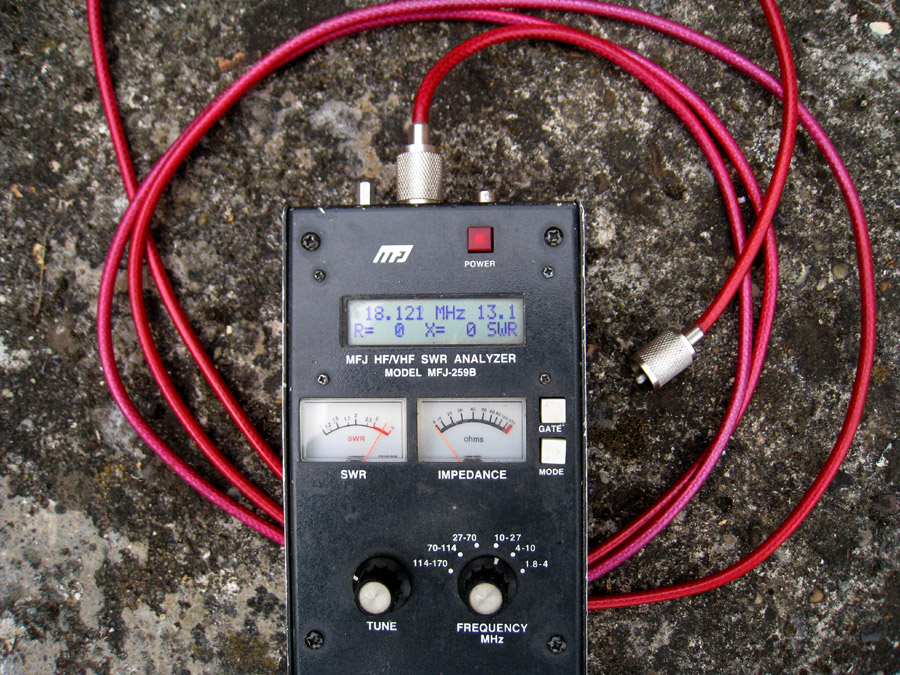
The ‘X Factor’ – X = ‘Zero’
Here we show you a section of 75 ohm coax hooked up to the analyser. The far end is open (although it does have a PL259 on it ready to connect up). It was trimmed for a quarter-wave at 17m (18.130MHz). You can see that X = ‘0’. You don’t need to take any other of the readings into account. This actual section of coax measured 3.21m which made the velocity factor (v/f) 0.78. The manufacturer claim on their technical data sheet was 0.80 so it was fairly close.
How to measure using your MFJ Analyser:
Select the first (or opening) measurement mode in the MAIN menu.
Connect the stub under test to the “ANTENNA” connector of the analyser.
Note: The line must be open circuit at the far end for odd multiples of 1/4 wave stubs (i.e. 1/4, 3/4, 1-1/4, etc.) and short circuited for all half-wave stub multiples (like 1/2, 1, 1-1/2, etc.). For our experiment, the far end of you coax should be ‘OPEN’ (i.e. nothing connected to it). Put an PL259 on the other end and connect it to the analyser.
Use the ANTENNA connector’s shield for one lead and its centre pin for the other.
Coaxial lines can be in a pile or coil on the floor, it makes no difference. Internal or external power can be used, and the analyser can be placed on or near large metallic objects with no ill effects. Coaxial lines connect normally, with the shield grounded. When tuning stubs, gradually trim the stub to frequency. Adjust the feed line or stub using the following method:
1.) Determine the desired frequency and theoretical length of the feed line or stub.
2.) Cut the stub about 15 percent longer than calculated, and short the far end for a half-wave (or multiple of a half wave) stub or feed line. Leave the far end open for feed lines or stubs that are 1/4 wavelength or odd multiples of wavelength long.
3.) Measure frequency of lowest resistance and reactance, or lowest impedance. For fine tuning look only at the “X=?” display. Adjust for X=0, or as close as X=0 as possible. The frequency should be about 15% below the desired frequency as we have cut the stub ‘long’ so it can be trimmed.
4.) Take no notice of the SWR or ‘Resistance’ readings. Begin to trim 1-2cms off the coax far end and re-take the reading. You will notice that the ‘X’ (reactance has gone down). Keep trimming until the reactance is as close to ‘0’. When you get close to ‘0’ fine trim at 1cm a time.
You now have a quarter-wavelength stub cut to the velocity factor of the coax at the frequency you are operating at.
Now you have successfully made your quarter-wave matching transformer, check out the diagram below which shows you how to get your loop up and running.
No Analyser? – not a problem
Working out the length of the ¼ matching section using 75 ohm coax with 0.66 velocity factor (v/f) for the 15m band:
First, find the value of a ‘Full wavelength’ on the frequency you are operating on. Let’s say we are operating on the 15m band (21.230MHz) and require a matching section. We use the following formula.
Wavelength = 299,792,458 (speed of radio waves in air) divided by the frequency. So 299,792,458 divided by 21.230 equals 14.12 meters. Then multiply 14.12 by 0.66 and you get 9.3324m. Divide by 4 (gives you a quarter) and your total length is 2.333 meters. You’ll need to know the approximate velocity factor of your coax then you’ll be close. Maybe not ‘spot-on’ but close enough.
Working out the length of the ¼ matching section using 75 ohm coax with 0.84 velocity factor (v/f) for the 20m band:
First, find the value of a ‘Full wavelength’ on the frequency you are operating on. Let’s say we are operating on the 20m band (14.230MHz) and require a matching section. We use the following formula.
Wavelength = 299,792,458 (speed of radio waves in air) divided by the frequency. So 299,792,458 divided by 14.230 equals 21.06 meters. Then multiply 21.06 by 0.84 and you get 17.696m. Divide by 4 (gives you a quarter) and your total length is 4.424 meters. You’ll need to know the approximate velocity factor of your coax then you’ll be close. Maybe not ‘spot-on’ but close enough.


