
Build a High Power 4:1 Guanella Current Balun RF Choke and Transformer Using 2 Cores
As with the 1:1 Balun, there’s plenty of online info on building 4:1 Baluns. I’ve seen and read many articles on baluns and there’s’ plenty of pretty variable advice out there.
A 4:1 balun is in reality a transformer, converting a high impedance [for example an impedance of around 200 ohms] back to a lower 50 ohms impedance. When this happens your transceivers ‘sees’ a better match and your SWR will be much better suited to your equipment. However, this must be all taken with a pinch of salt as impedance with transformers will vary with frequency – especially on multiband antennas and of course the hardware used to build that transformer.. What looks ‘good’ say at 40m could [potentially] be way out on other bands.
Let’s for starters consider the two types of balun on offer. The first is the ‘Voltage Balun’. This variant always tries to force the output terminals to equal voltages. This sometimes introduces a phase shift between each output terminal and ground. If the impedance presented is not fairly closely equal at both terminals, the feeder and load currents will not be equal and opposite meaning there could be some feedline radiation. Exactly the reverse of what you don’t want.
This type of balun is also [or can be] inadequate at providing reasonable common-mode isolation and stopping common-mode currents flowing on the braid of the coax. Theory says that a voltage balun will almost certainly guarantee some feedline radiation because there are very few perfectly balanced loads or perfect voltage baluns.
A good common-mode choke will need to present a choking impedance of at least 1000 ohms minimum [and preferably twice that or more] at the operating frequency. A very good ‘RF choke’ will be 5k ohms and often more. Some constructors will use a 4 to 1 Voltage Balun [Such as a ‘Ruthroff‘ Design] with a ‘Guanella’ 1:1 Current Balun in series to provide both the impedance transformation [4:1] 200 to 50 ohms and then the 1:1 unit is used to provide the RF choke.
Unlike a current balun, a voltage balun will always energise its core in direct proportion to load voltages. In a voltage balun, load impedance directly affects core heating and flux density. Current baluns therefore should be used whenever possible. Current baluns provide better balance and more often than not – have lower losses.
Another piece of misguided information is how many online articles relating to 4:1 baluns show only a single core design. On the surface, the design is simple and easy to construct and as a bonus, only uses a single ferrite core, but in practice it’s not the best choice.
You can find plenty of single core ‘Ruthroff 4:1 Voltage Baluns‘ using a T200-2 iron toroid.
A single core 4:1 Voltage Balun is a poor choice – IMO.
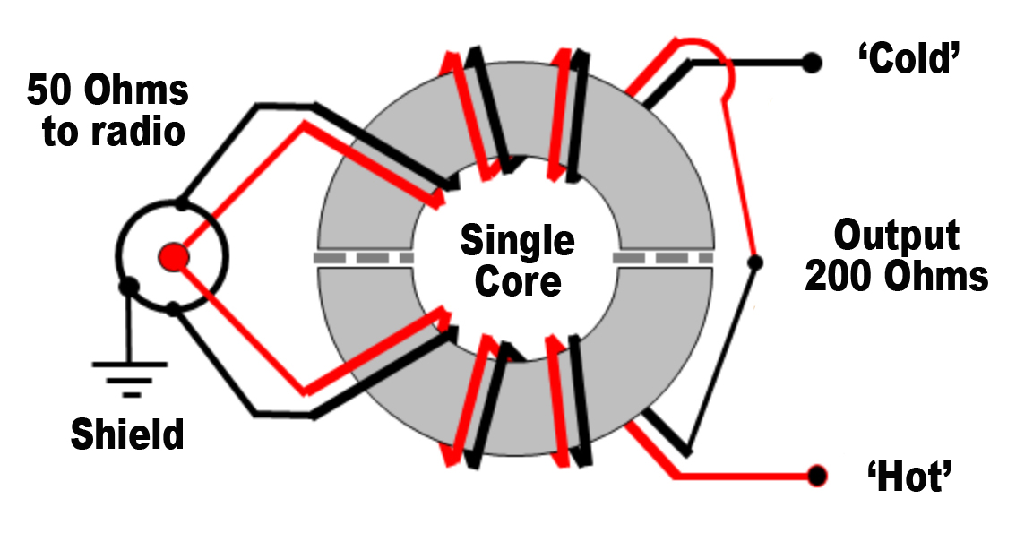
This shows dual windings on a single toroid. This doesn’t work well. In order for a 4:1 balun to work correctly, TWO separate cores should be used.
I did find an interesting article here on QRZ.com where WB2UAQ did some return loss tests between a single core 4:1 Balun and a dual core version using type 43 ferrites. Return loss in the dual core version was excellent, generally over 30db.
Expert analysis from stalwarts such as Steve Hunt G3TXQ [sk] and Owen Duffy VK1OD explain in detail why they don’t’ work.
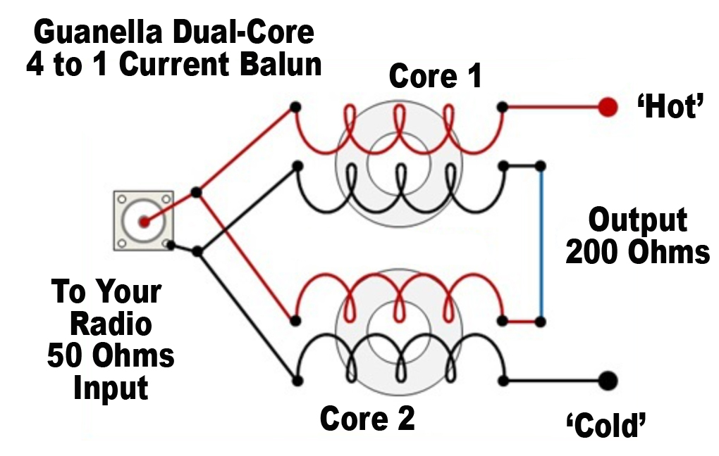
Given the short comings in a 4:1 Ruthroff design – let’s look more towards a 4:1 balun that will do a better job. Enter the 4:1 ‘Guanella’ balun. Unlike the Ruthroff design, the Guanella is a 4:1 ‘Current Balun’.
Current baluns allow each output terminal voltage, with respect to ground, to float and provide equal currents to each feedline conductor. Current baluns isolate or add impedance to unwanted common-mode current paths thus making them great for choking off unwanted feeder radiation. Current baluns are the balun of choice nearly in all situations because they work much better than voltage baluns, providing better balance and lower loss in most real-world environments. Current baluns make great isolators.
When it come to the choice of cores, the same applies as to 1:1 Baluns, however, there is a caveat with the Type 31 core. The normal choice for the low-band aficionado would be the ‘Type 31’ such as the FT240-31 core which is optimised for 10MHz and lower. However, experts at ‘Palomar Engineer’s‘ in the US say that using a type ’31’ core in a multi-ratio impedance transformer [i.e. anything that is NOT 1:1] is not recommended. In essence, using it as a 1:1 RF Choke Balun for an 80m antenna would be fine, but as a 4:1 transformer on a 40m antenna wouldn’t.
Given the above advice, we’d steer towards a good ‘general core‘. A ‘Type 43’ such as the
FT240-43 is a good choice, and for more higher-band choking impedance and match, we’d suggest the FT240-52 or ‘K’ type ferrite which is a solid ‘All-rounder’ or even the FT240-61. The later would be good for 10MHz upwards and continued advice from Palomar say it’s a good choice of core for use in high-power multi-ratio [such as 4:1 or 9:1] baluns and un-uns.
I settled on FT240-52 cores for this project as in the past, I’ve constructed both 1:1 and 4:1 baluns using the same core material with great results. There’s a similar 4:1 unit currently in use here at the station feeding a single element 80m delta loop antenna. The end user therefore has a few choices depending on where they operate in the spectrum.
The input is an SO239 and output is 2 x M6 stainless pins. Resistors of 200 ohms simulate the load impedance
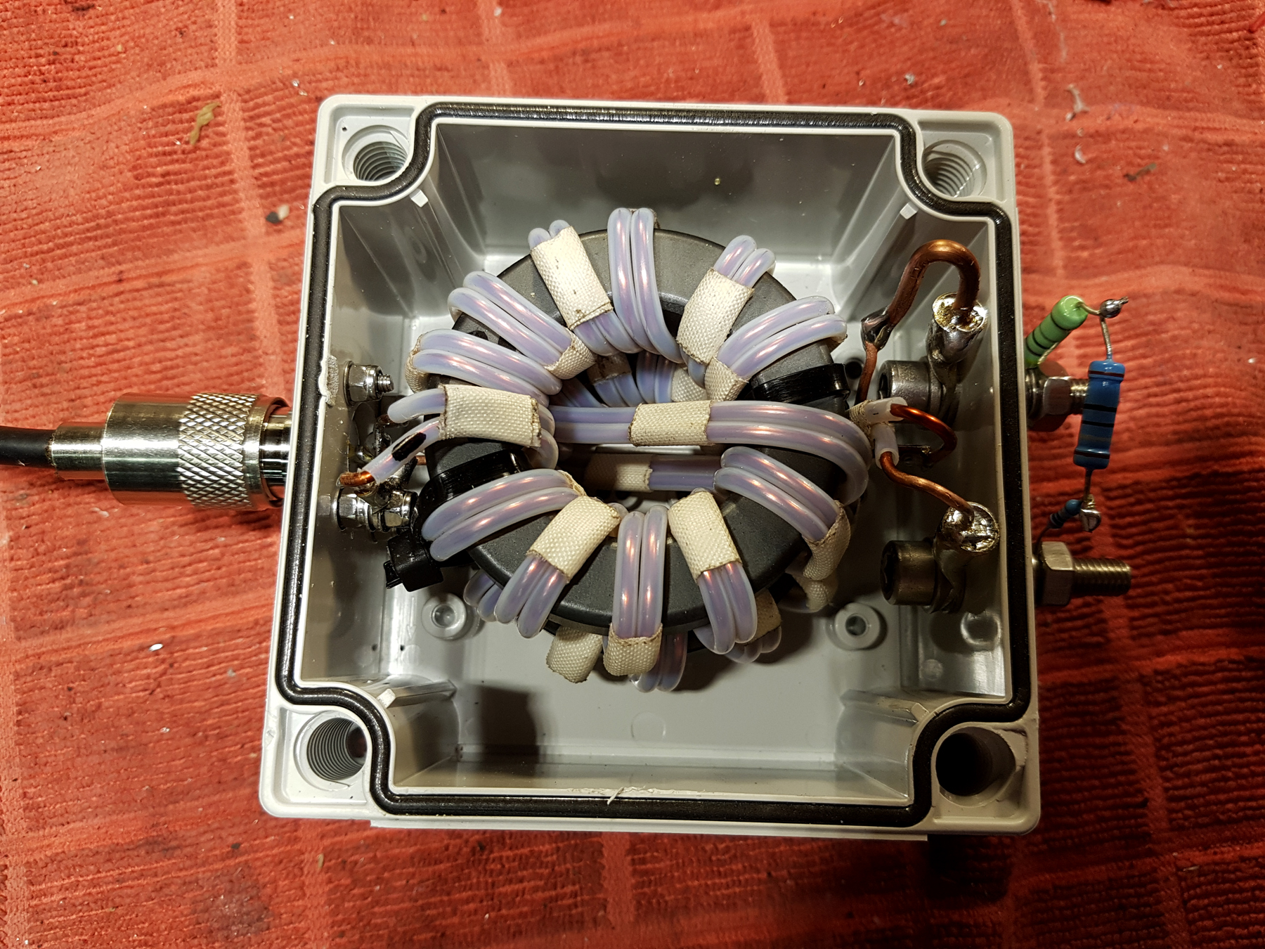
In winding the cores in the above Guanella balun, a ‘Bifilar‘ winding is used. Bifilar winding uses two wires [side by side] and wound around each ferrite core. The windings are secured using ‘Scotch‘ fibreglass tape which keeps the windings true and parallel to each other. The amount of optimal windings can vary depending on the frequency and type of core. For this experiment, I’m using two FT240-52 ferrite cores [aka ‘K’] ferrites with 12 windings on each core which should give a good wideband coverage. The wires being used are 14AWG [or 1.70mm] dual coated enamelled magnet wire.
You may notice that the windings loop back over and through the core at the halfway point. This is to reduce the amount of shunt capacitance in the windings. There’s plenty of online debate as to whether this is a good thing or not. In the past I’ve found that it moves the ‘Sweet Spot’ in reducing common mode currents further up the band. But for this exercise, we’ll retain the above method [rather than just wind side-by-side continuous around the core] as it seems to work well for the design.
Each wire has additional insulation in that it’s passed through a very fine ‘PTFE‘ tube [3mm outer diameter and 2mm inner] . The result is a parallel transmission line which is approximately 4mm between core centers. We’re after an ideal 4mm which gives us 95 ohms on the line [close to the desired 100 ohm requirement].
For constructors wondering why we use a small PTFE tube. PTFE is an excellent insulator [in this case it provides over 11kV] and subsequently allows increased power handling. Using this configuration, the balun should easily handle in excess of 2Kw.
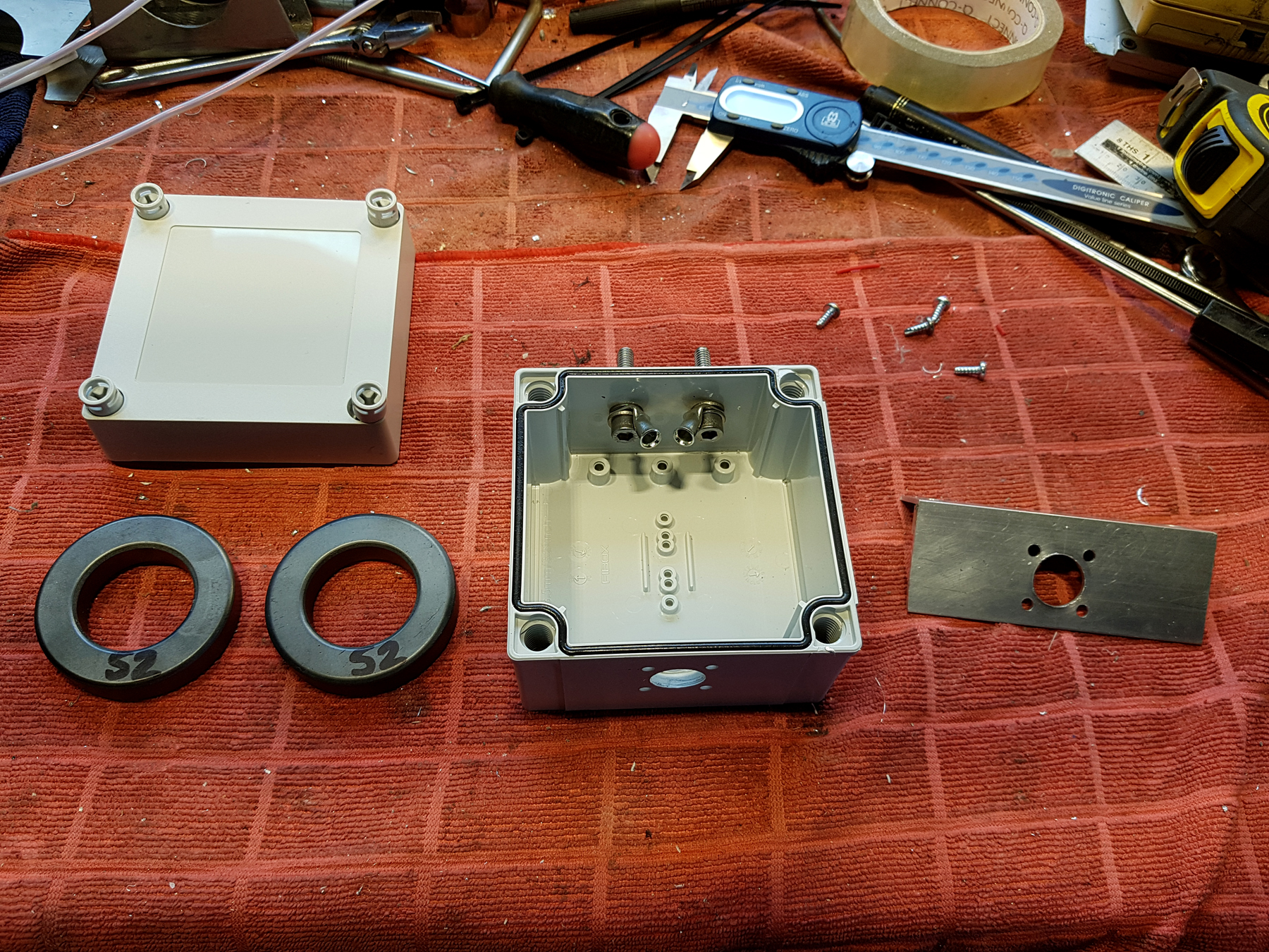
So, continuing with the project we move onto the box. I’m using a trusted RS Components ‘Fibox’ enclosure. These ABS boxes come in many different sizes and make great project boxes. As an additional bonus, they are ‘IP67’ rated, meaning they are good for most outdoor weather conditions as the lid includes a small sealing gasket to keep water out. I would say as a caveat, I think it’s best to add a couple a small [M4] breather holes in the base of the box. This prevents moisture build up and, if by any chance the box does start to fill with water – then there’s an escape hatch so all your handy work isn’t ruined.
I used a previously constructed homebrew ‘template’ for the SO239 drilling location which ensured accuracy
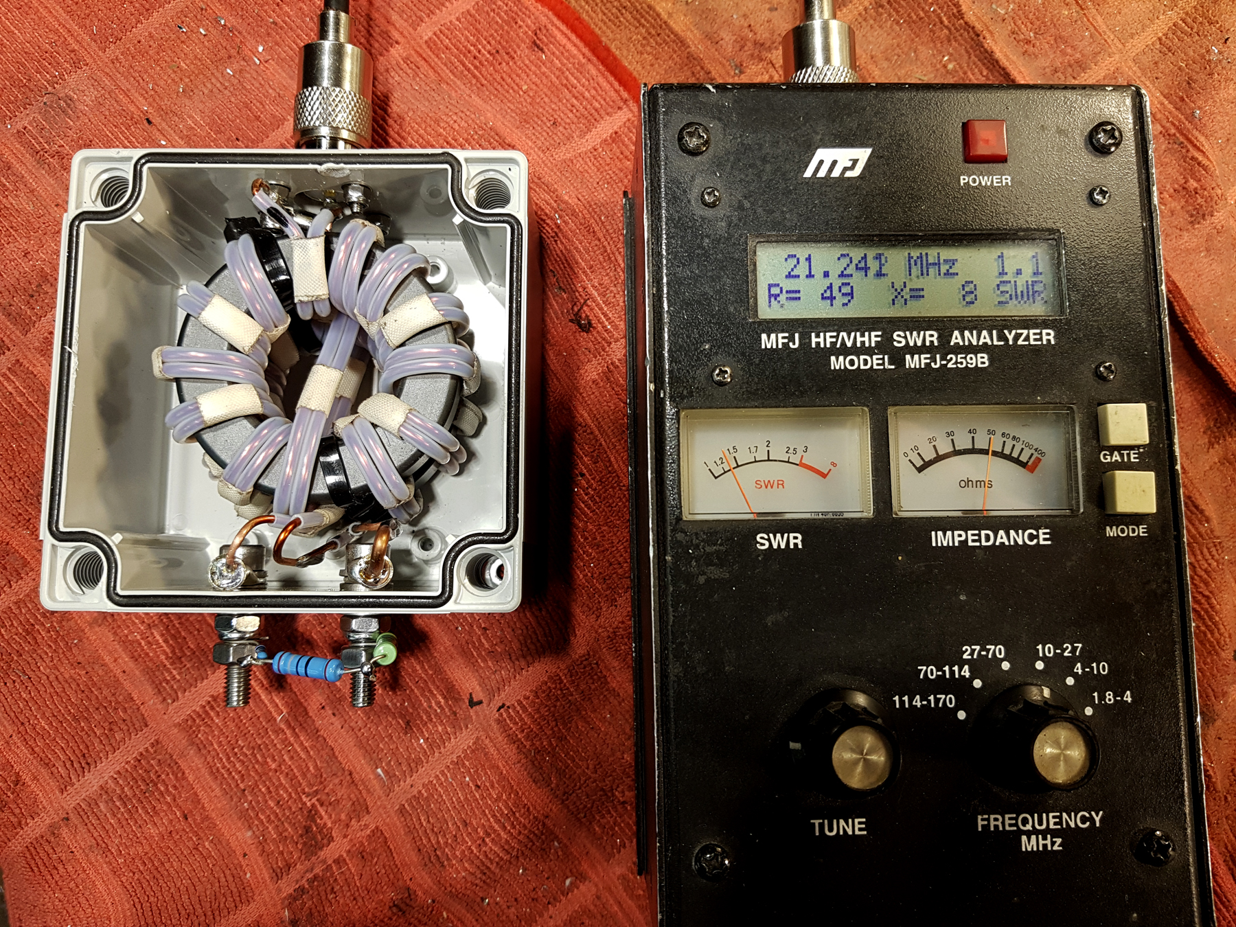
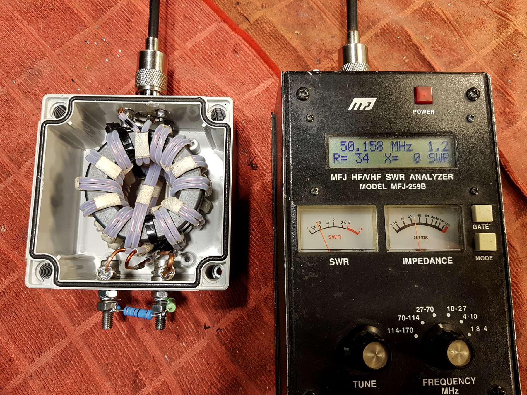
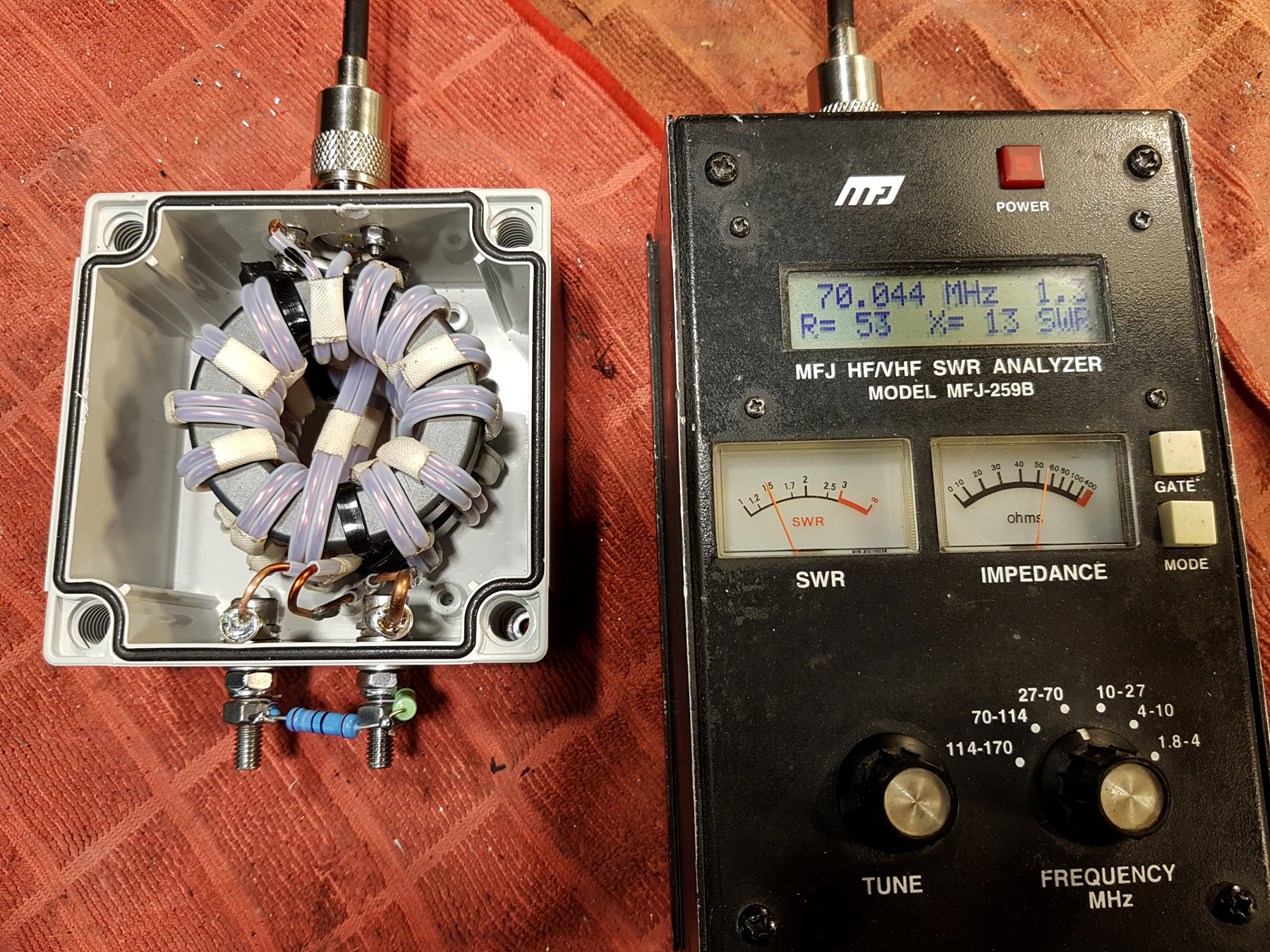
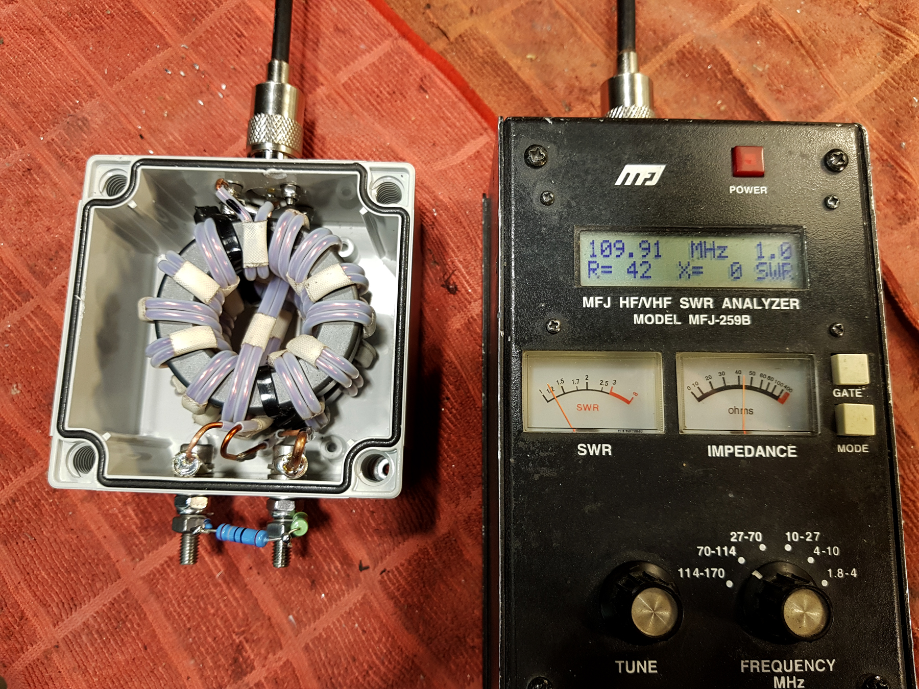
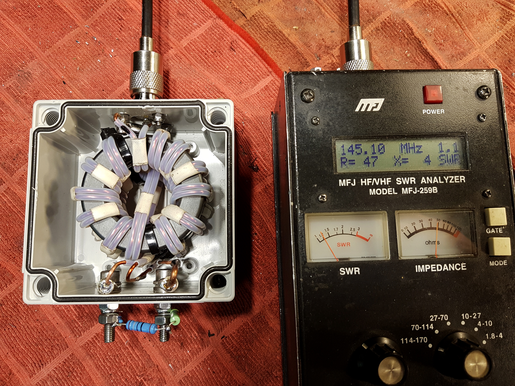
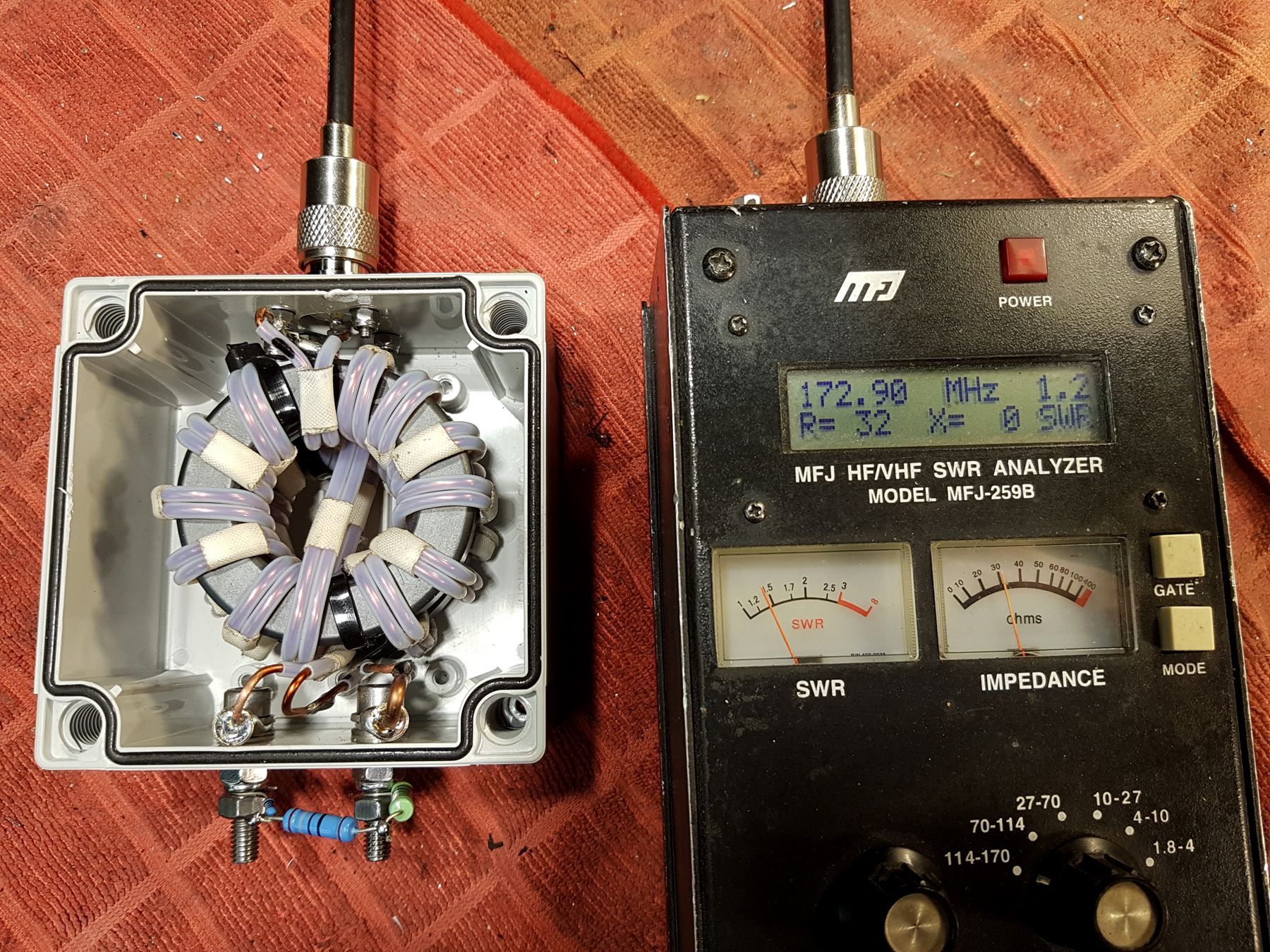
Construction of both cores, winding and the fitting of the cores and doing all the ‘fiddly soldering work’ took a whole afternoon but was well worth it. I expected the design to be ‘good’ from top-band [160m] up to 6m [51Mhz] – that would have been sufficient. However, when testing, I found the balun had exceptional return loss all the way up to 173Mhz. It would probably perform reasonably well with even higher frequencies but my trusty MFJ259B topped out at this frequency and my VNA [which had developed a fault a few months prior] had yet to be fixed – therefore further testing into VHF was not possible.
So, here’s the images taken with an MFJ259B. There’s a small 50cm patch lead of RG8 Mini running from the analyser to the SO239 input of the balun. Non-inductive resistors totalling 200 ohms are fixed to the output pins to simulate the load impedance.
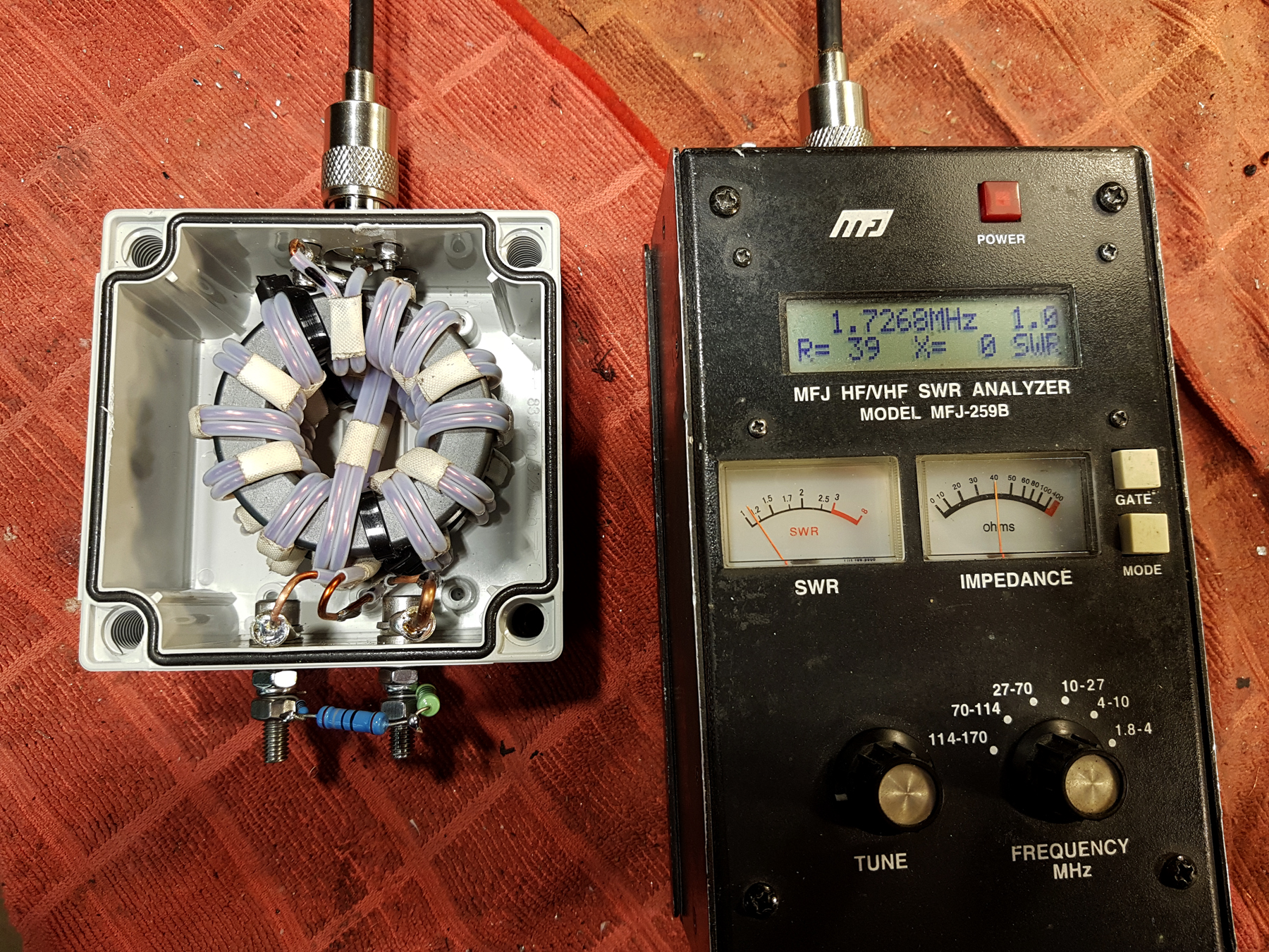
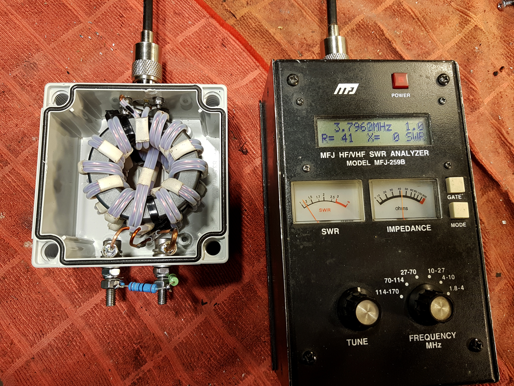
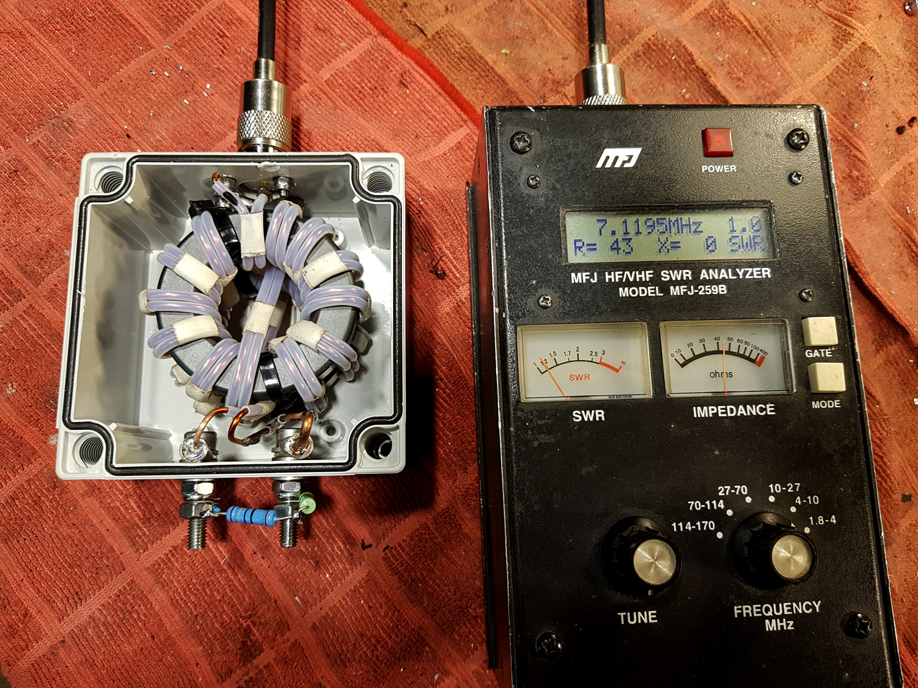
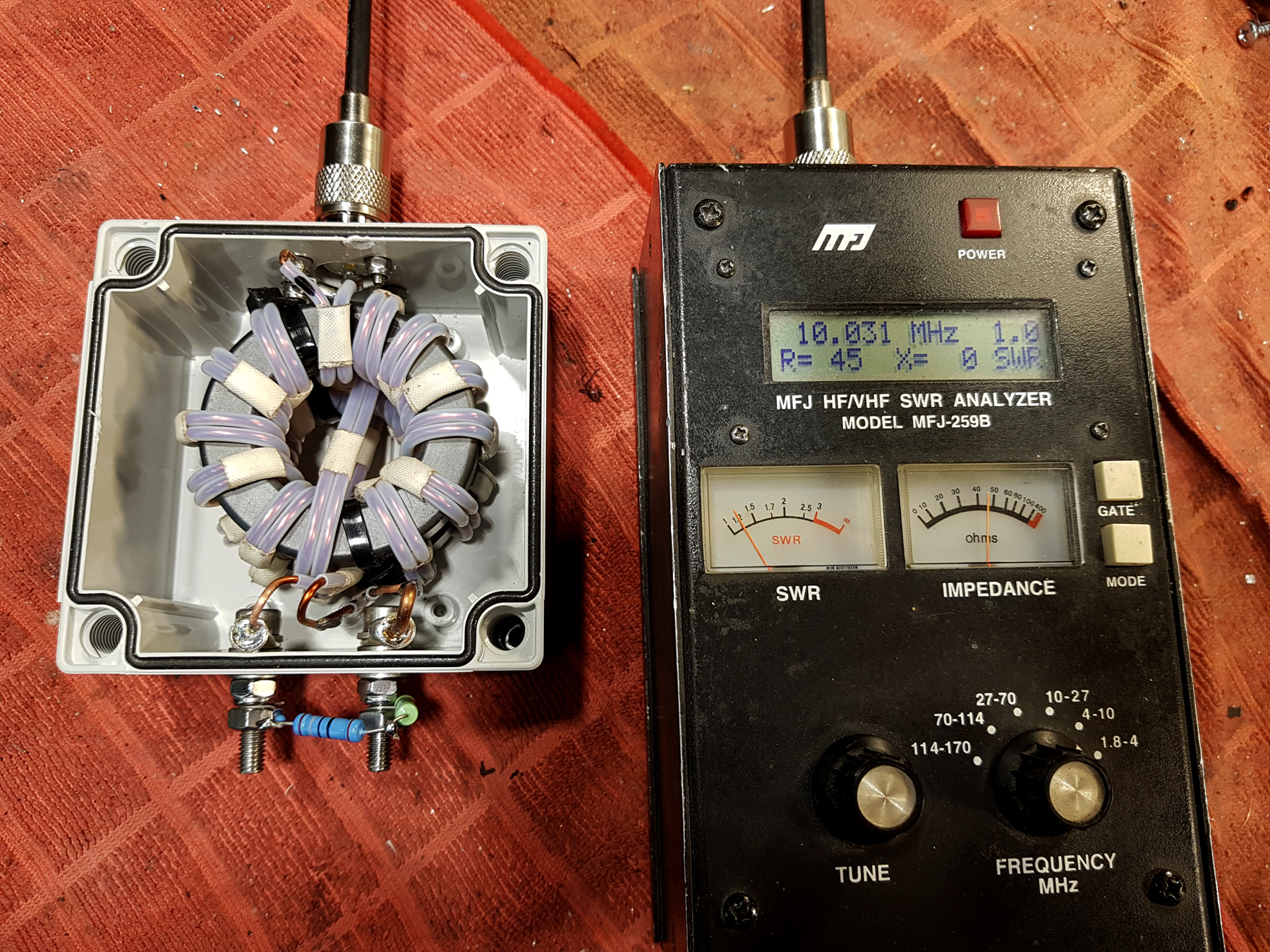
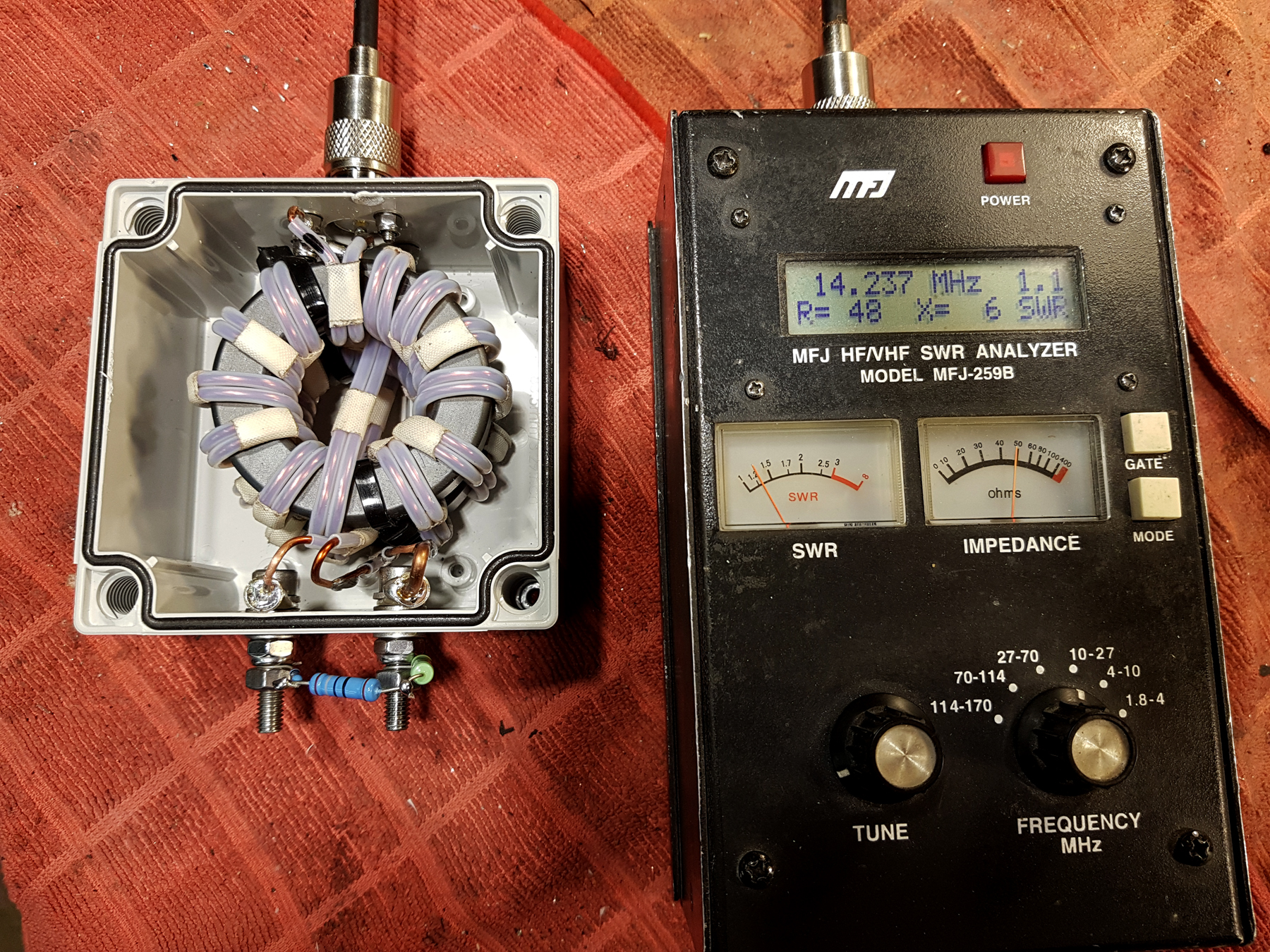
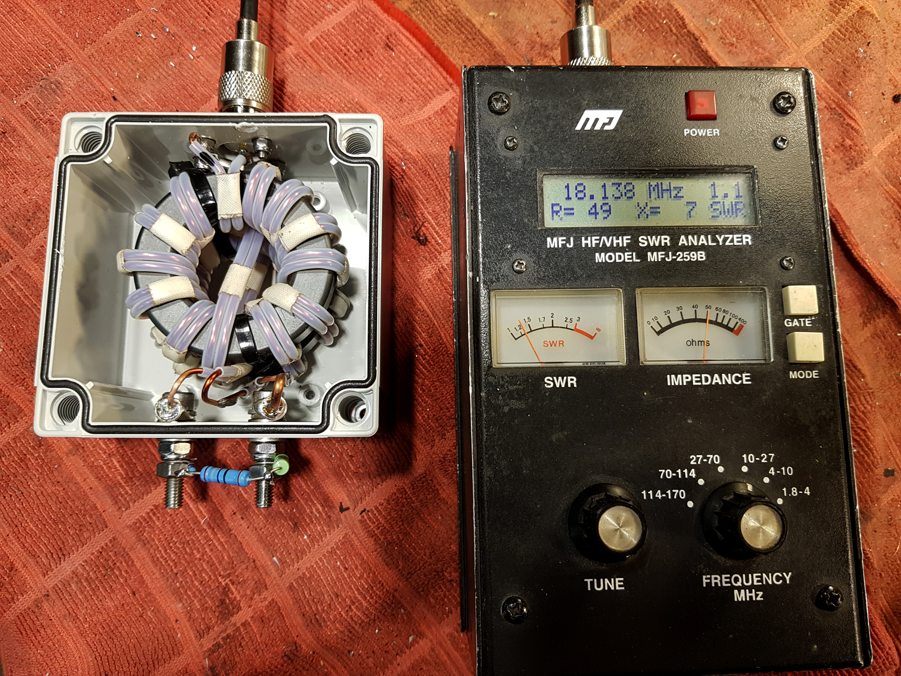
I wonder whether there is some small reactance present in the resistors at certain frequencies

*Summary and Approximate Cost:
All-in-all a very worth while project. Baluns with quality and construction such as these retail for well over £120 here in the UK and [most] are imported. Here you can build your own unit for under half that price. Good luck with your project!
Fibox Box – £9.00
2 x FT240-52 Ferrite Cores – £13.00 each
PTFE Tubing – £8.00
SO239 Socket [PTFE Dielectric] – £3.00
Stainless Hardware and ancillary items – £2.00
Total = £48.00
* Correct at time of original publication [01/2022]

