
Match a Yagi with a Hairpin Match
When building any antenna system, the builder will need some kind of matching system if the antenna is not resonant around the 50 ohms point. Many high-performance monoband Yagi’s exhibit feed point impedances of around 25-35 ohms.
If you feed this directly without any matching, then your SWR curve would be abnormally high and the antenna will exhibit a very narrow bandwidth.
Fortunately for builders of Yagi antennas with low feed point impedances, there is a very simple but very effective low-loss and low-cost solution. Called the ‘Hairpin Match’ or ‘Shunt’ [mainly because it looks like a glorified ‘U’ shape when installed] – it gives the user great control and setting it is simplicity in itself.
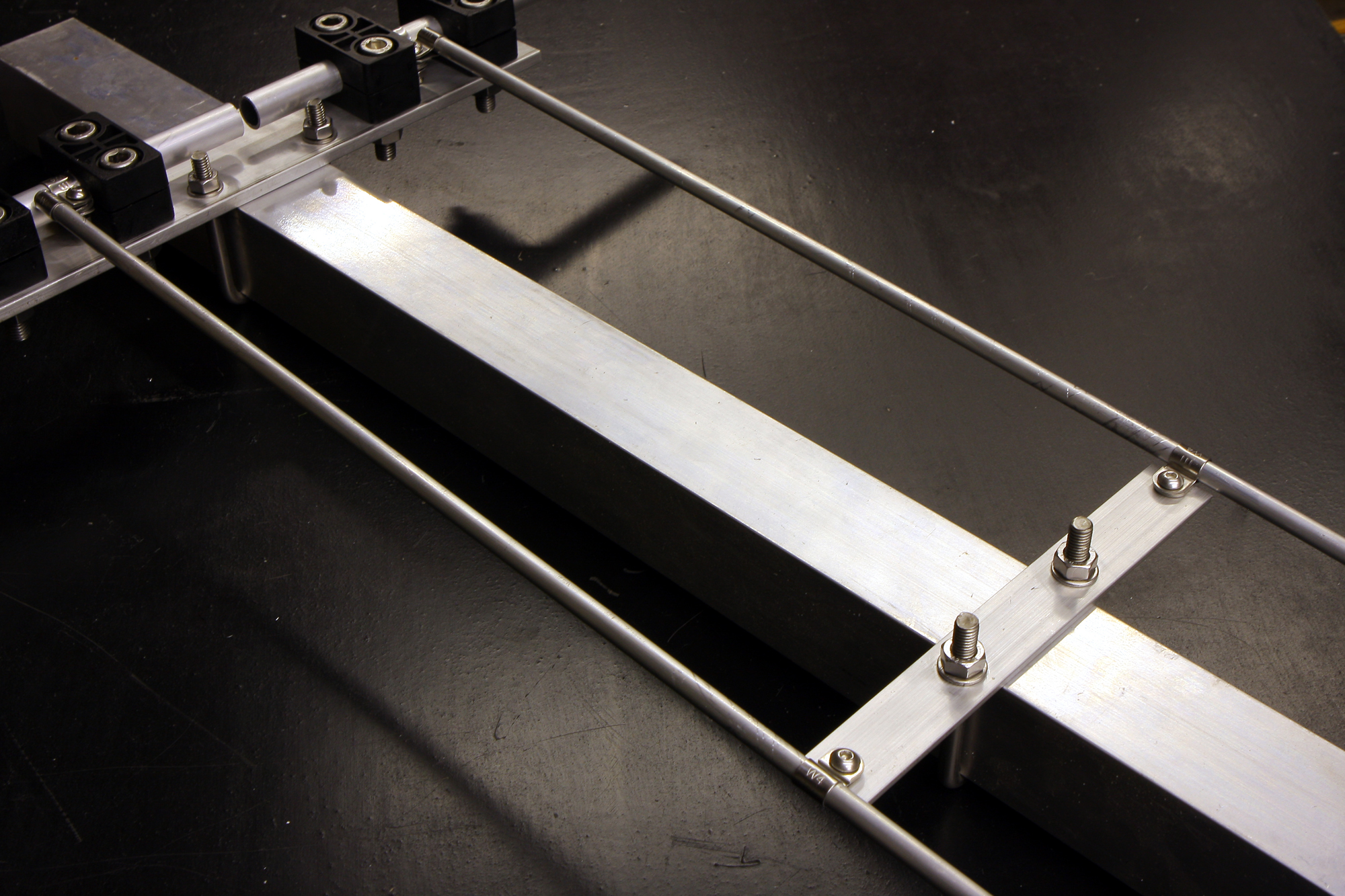
The way it works is rather than use a piece of ‘U’ shaped wire, you can use rods [copper or aluminium are best] that run parallel to the boom. You then have a shorting bar connected to each rod. The shorting bar can be moved up and down the rods. By moving the bar, operators can quickly match the Yagi antenna by repositioning the shorting bar along the hairpin rods. This way, the antenna is easier to adjust for minimum SWR than conventional wire-loop hairpins.
To hold the shorting bar in place, normally two holes are drilled through it, and it attaches to the boom with a U-Bolt which can then be set at a fixed point when the correct matching position is known.
What does the hairpin match do? Simply put, the hairpin adds inductance across the feed-point and at the same time reduces the amount of reactance ‘X’. The amount of inductance required to offset this reactance is controlled by the position of the shorting bar.
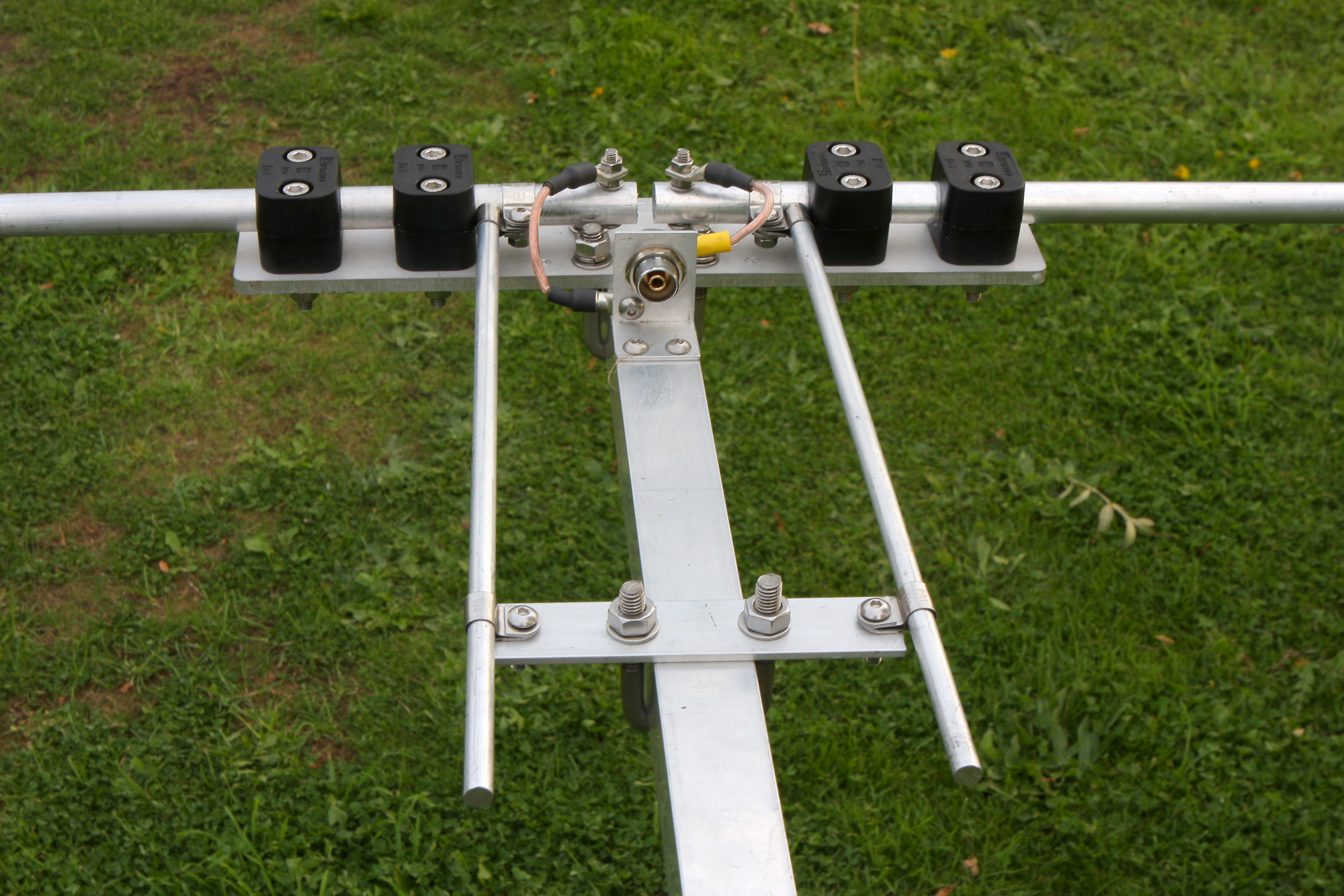
An additional bonus, as the shorting bar is attached to the boom – it puts the whole antenna at a common DC ground.
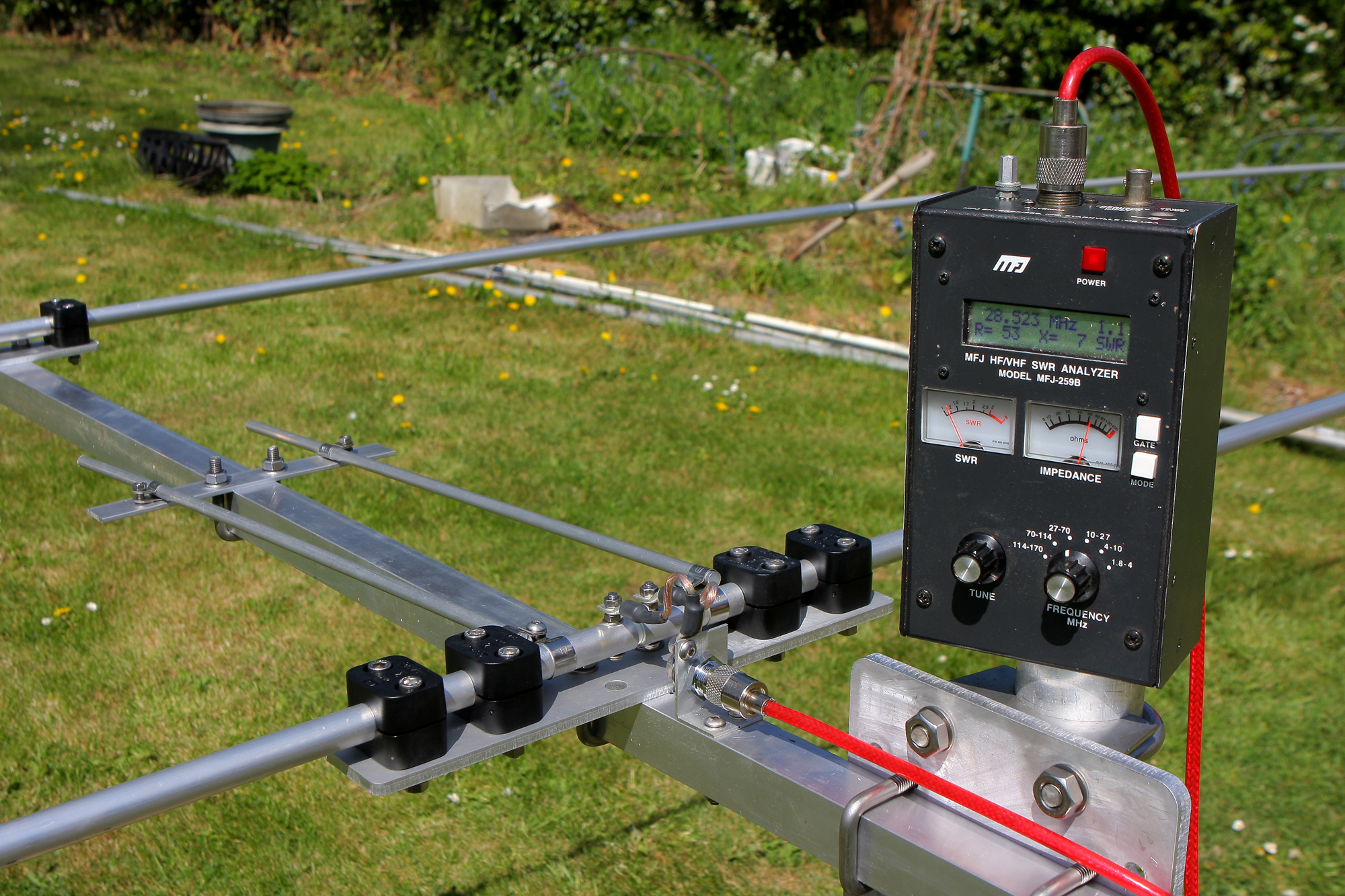
Hairpins are normally used with a ‘Split-Dipole’ style driven element and the good thing here is that the unmatched impedance prior to fitting the hairpin can be measured with any modest antenna analyser. During tuning, the driver may require some minor adjustment to hit the sweet spot, but certainly in my own experience, getting a match is a fairly straightforward affair.
The hairpin match is also a better solution for matching a Yagi antenna rather than a gamma match. We’ve heard stories of some Yagi antennas with a gamma match having issues of high SWR especially during wet or damp weather probably due to moisture ingress. A good gamma will normally work well if properly sealed but this needs to use a quality PTFE insert as the dielectric. Many cheaper budget antennas we know of don’t use PTFE but nylon which we wouldn’t recommend.
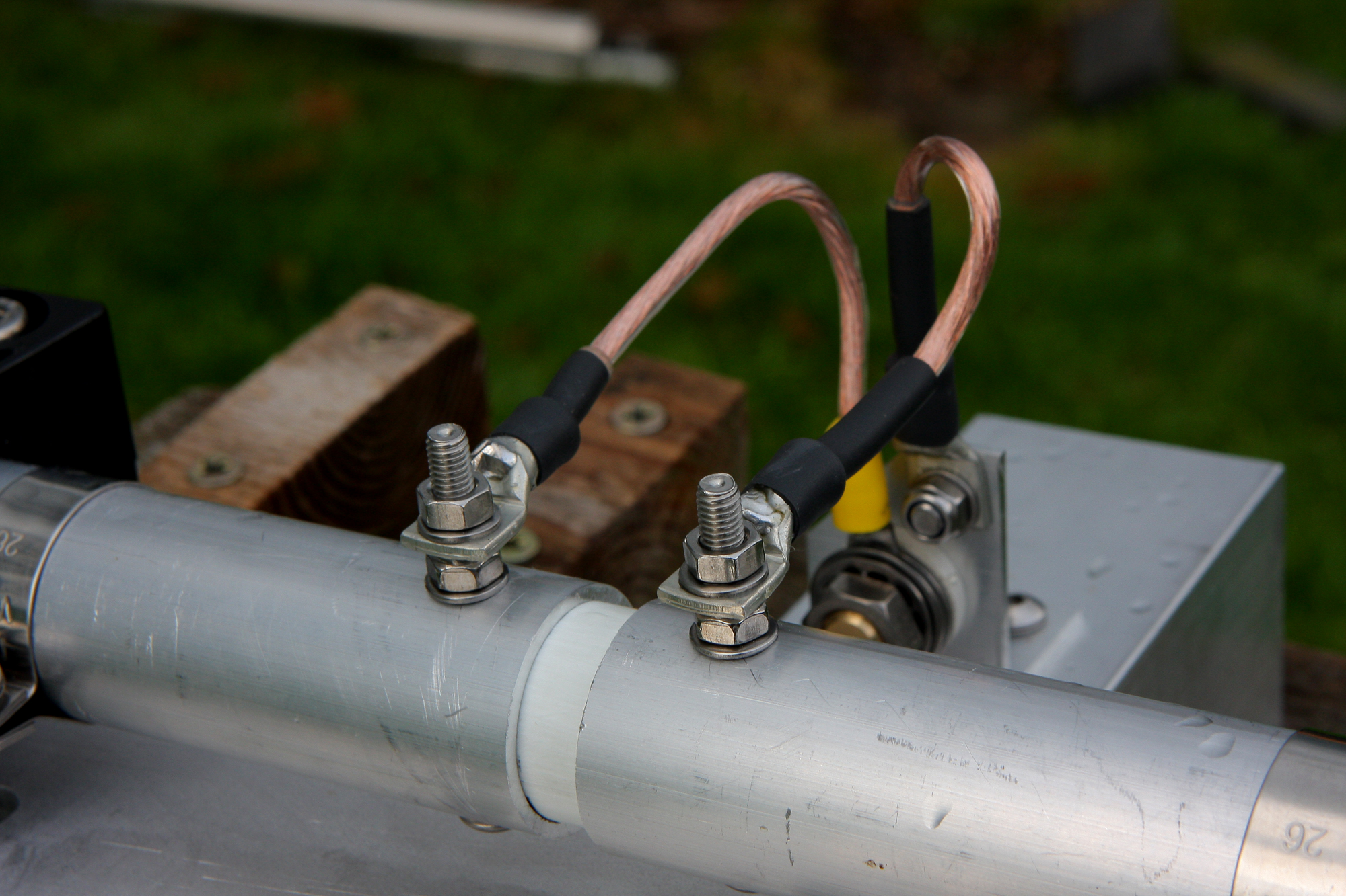
After matching is completed you have a fully ‘Balanced Antenna’ – however it is being fed with unbalanced coax. The majority of builders will decide to fit a *1:1 ferrite choke balun at the feed point to eliminate common mode current on the feed line. These currents flow on the braid of the coax and can severely distort the radiation pattern of the antenna. So, although the balun is perceived as just an ‘Optional Extra’ by many, the purists will definitely choose to fit one.
*A word of caution on baluns. You can fit a cheap and cheerful air-cored balun just by winding a length a coax in a coil. However, they are generally very narrow-banded and unless you have access to a good VNA or equivalent test gear to measure the choking impedance, then they are best avoided.
Check out the site for various balun projects and in particular this 1:1 RF Feedpoint Choke would suit this project well..

