
Here’s a design based around a 2 element Yagi on both the 30 and 40m bands. The idea is that at some time soon as the higher bands drop away, maybe in the Autumn of 2026 or the Spring of 2027, I will remove the big 6 element 10m Yagi that’s been on the tower for a while and have a try on both 40 and 30m to get my 300 DXCC for both of these bands.
There’re a few commercial designs around for this antenna, but none would suit my QTH. I have limited space between the tower and the surrounding trees, but because we live in a protected area – felling trees to make way for antennas is out of the question.
I have based this design around a maximum element length of 12m which of course is the 40m reflector being 6m each side. This represents 58% of full size. On 30m, the antenna is still short but at 67% of full size. The boom length is around *5.7m which allows for a small overlap at each end. Element to Element distance on 40m is 5.5m and 3.68m on 30m.
Click on the image above for a hi-res PDF [Opens in a new tab]
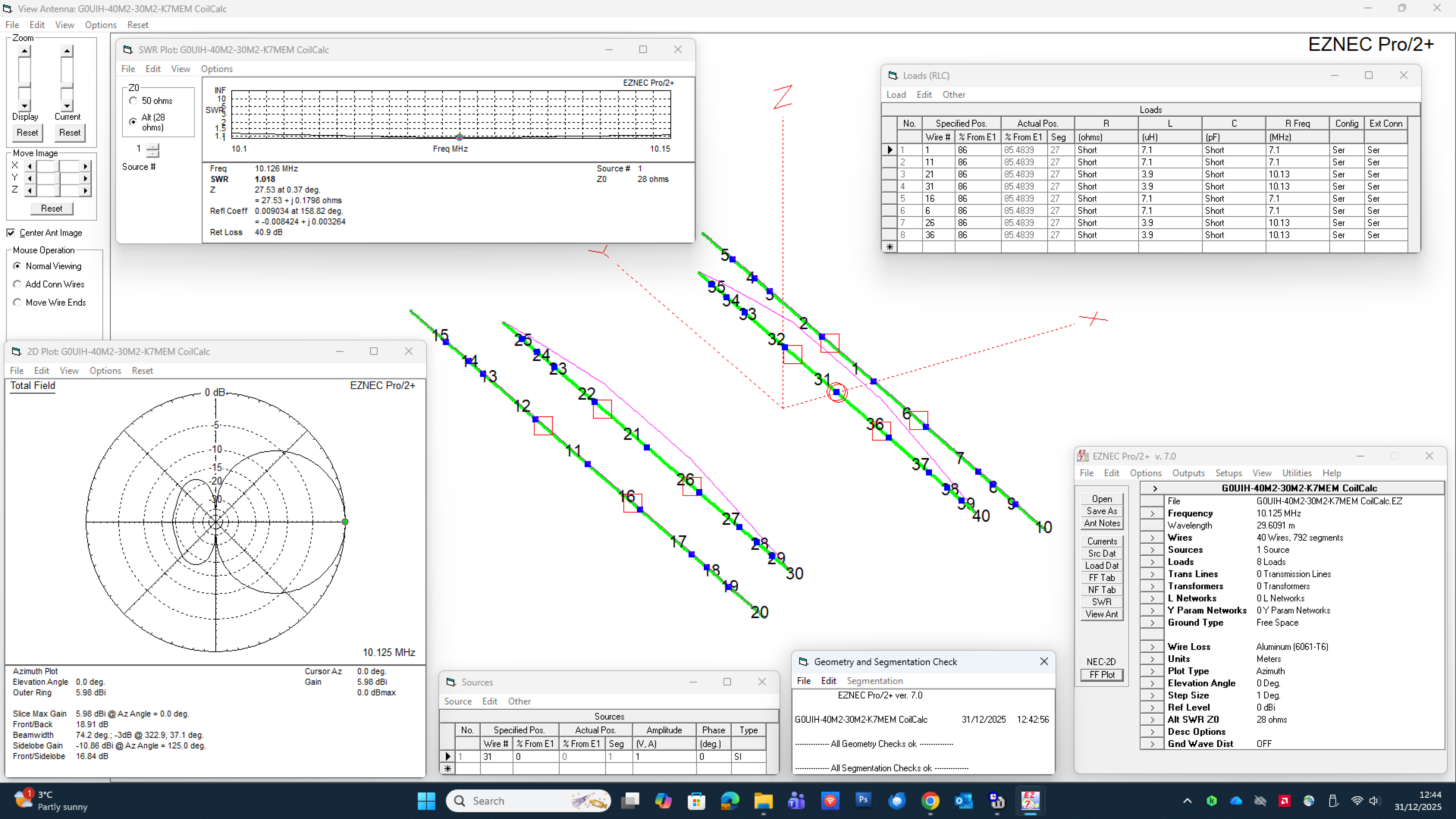
The antenna has been modelled using the coil modelling utility by K7MEM. I have placed the coils at around 1.5m from the element centre of the boom. From the online info, this should give all coils a theoretical maximum [or close to maximum] ‘Q’ based around the design. Coils are mounted on the 30mm diameter tube at 1.5m from boom centre [all elements]. The remaining 30mm tube then telescopes into the 25mm tube.
Calculated coil inductance is 3.9uh for the 30m band and 7.1uh for the 40m elements. As we know, getting coils to be precise [could] and may well be challenging. My suggestion is that once you have a coil that’s as close as you can get it for the first band, manufacturer it and then duplicate 3 more.
Check the inductance using your ‘LCR meter‘ and then, if necessary, change the coil value in the EZNEC file and then re-run the model. You may find that it’s easier to do this and then perform a minor adjustment on element lengths accordingly. Just be aware that because both bands have shortened elements, changing data in EZNEC will result in changes especially in reported gain and front-to-back figures. Any changes will be more noticeable in the 40m design as this is shortened the most.
I’m happy that on 30m the antenna has a natural impedance of around 28 ohms and should give a nice low SWR when matched with a [not so long] hairpin match.
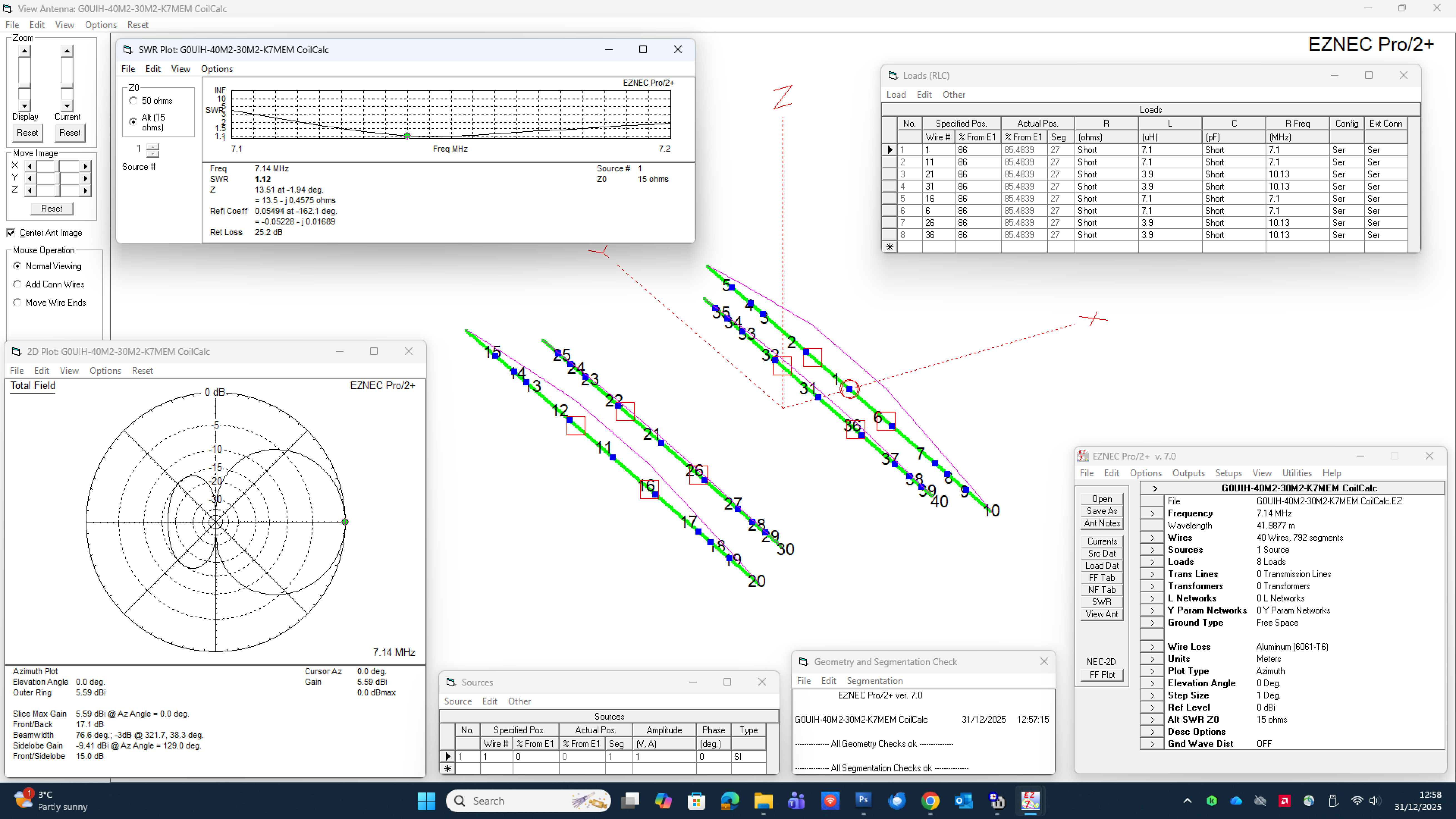
On 40m the antenna is somewhat overly short and because of this, the bandwidth suffers. In my own mind I would have liked a slightly lower SWR below 7.100MHz to include the FT8 area around 7.074 – but as I have [a very good] homebrew ‘L’ ATU, this won’t have any trouble matching out any reactance present below 7.100Mhz.
Click on the image above for a hi-res PDF [Opens in a new tab]
The natural impedance on 40m is quite low [around 12-15ohms] but the antenna is very useable when matched again with a hairpin match. The hairpin may well be long getting down to 12 ohms – so a ‘coiled hairpin‘ inductor may well be a better proposition rather than long rods.
What is noticeable is that each band does seem to interact with the other – but in a positive way. If you check the front-to-back ratio, on both bands there’s a distinct increase in some parts of the band. For instance, on 30m, the front-to-back is 19.73db on 10.100Mhz dropping only to 18.47db on 10.130Mhz. Normally, a 2 element Yagi would at best only have about 10-12db front-to-back ratio.
The same applies to 40m where at 7.100Mhz the front-to-back ratio sits around 8.65db which is a little low but increases to 12.9db at 7.110Mhz, 18.66db at 7.120Mhz, 21.38db at 7.130Mhz, 17.10db at 7.140Mhz and 13.70db at 7.150Mhz. As you can see, I’ve tried to optimise the front-to-back in this small part of the SSB section so you have the front-to-back ratio approaching that of a 3 element Yagi. Certainly useful for 40m SSB working.
When it’s been built, I’ll expand on the actual build and report back any findings here.
Here’s the current top-level rundown
- Longest element [40m Reflector] is 12m [6m per side]
- *Boom length between elements is 5.5m [5.70m allowing for end sections]
- 30m Gain is just under 6.00dbi
- 40m Gain is just under 5.30dbi
- Front-to-back ratio on both bands is positive [up to 21.38db]
- Great for those that don’t have too much space
- Covers all of 30m with ease
- Optimised for the 7.10 to 7.20Mhz SSB section of 40m
- Could also be re-modelled for the CW/Data sections of 40m if required
- Recommended to be mounted at least 15m above ground [20m is best]
Link here to the EZNEC File
EZNEC Pro/2 modelling software is available free of charge here from W7EL
Let me know if you build it and how you get on.
73 and good luck – Steve G0UIH

