
UPDATED: March 10th 2026
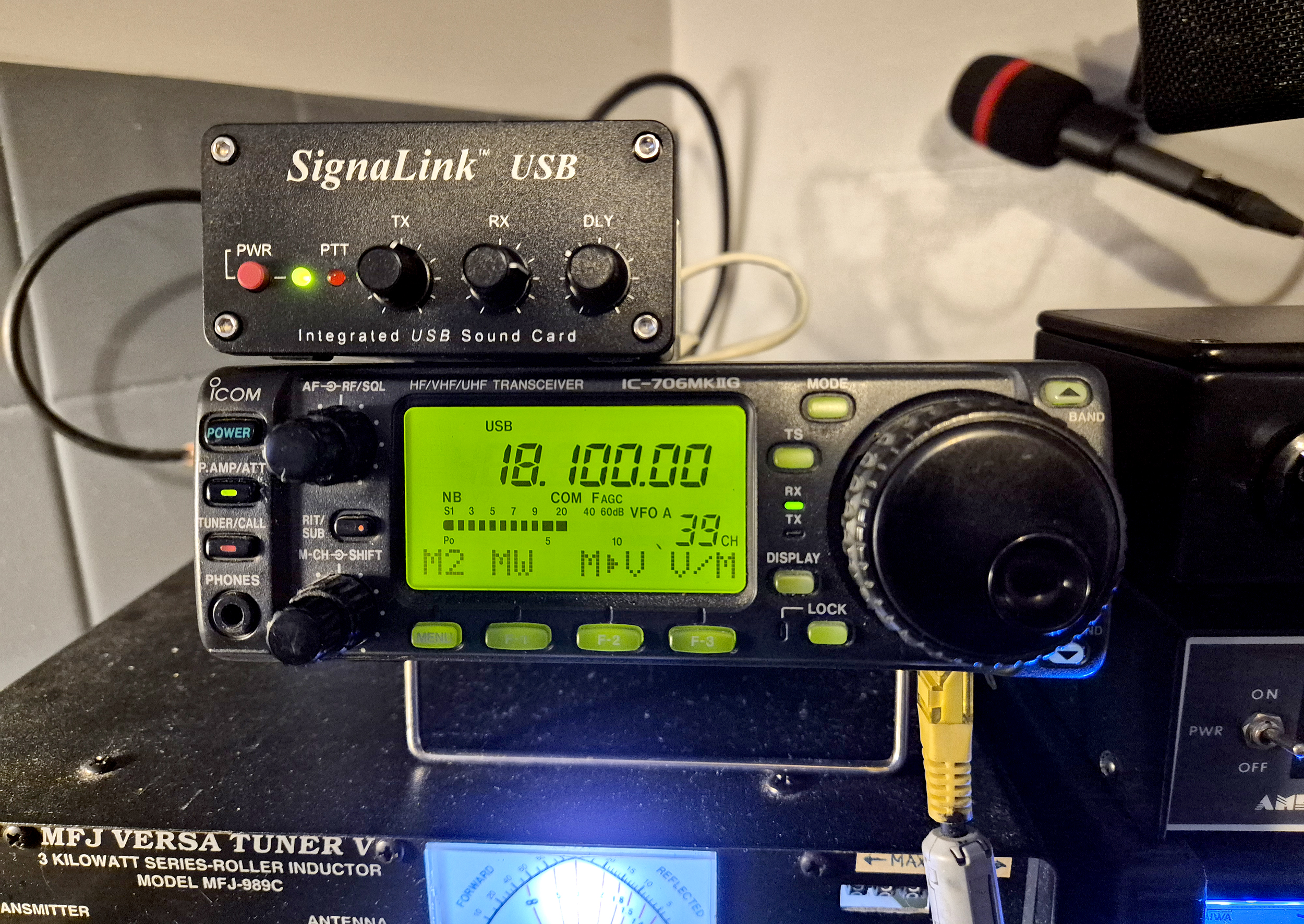
The Tigertronics SignaLink USB is a very popular small interface that enables users to hook up older radios to their PC and thus enable more modern Digitalmode operation such as FT8/4 etc. So, after my trusty Kenwood TS990 threw a wobbly and needed repair, I pushed my old IC-706MKIIG into service. In all the faff, I managed to pick up a used but mint SignaLink USB unit for £50 off eBay. However, getting it working from the outset was proving rather a challenge. Read this article to get your IC-706MK2G up and running in a few easy steps.
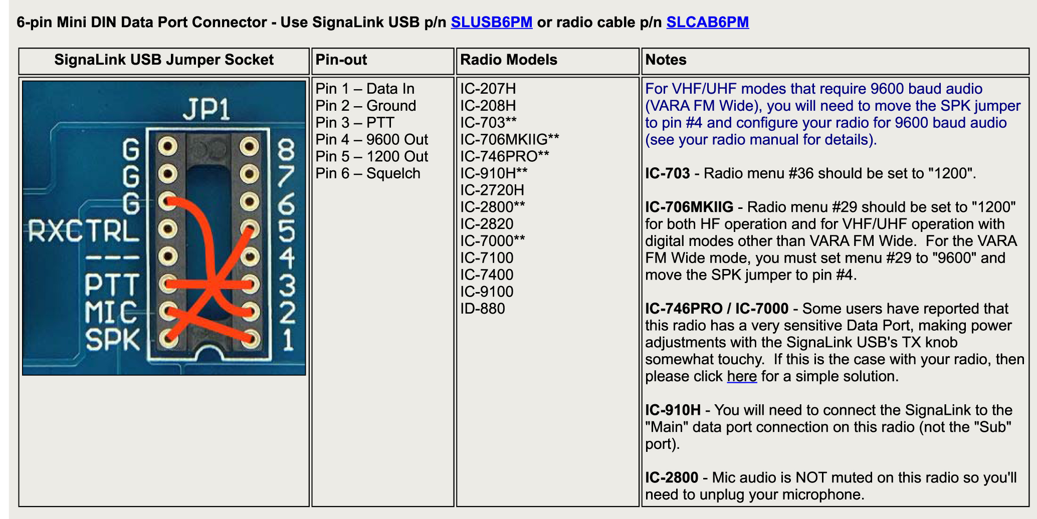
There’s plenty of online information including comprehensive help on the Tigertronics site. With all radios, the SignaLink USB firstly requires the jumpers to be correctly set inside the unit and these must match you radio. There’s a definitive guide here.
I’m not going into the many 100’s of different configurations that are possible with every radio – only to highlight the things that I found ‘Worked’ [and didn’t] when trying to setup the unit with my Icom IC706MKIIG.
Following the enablement of the jumpers [more info below], you’ll normally require three leads to get everything going, but read on as there’s an issue when using the ‘ACC2 ‘ 13 pin connector on the rear of the radio. Also the audio input to the Signalink unit is too low from the 706, so you need an extra lead [Lead 3] with info below.
Lead 1: SignaLink USB Unit:
A USB ‘B’ connector lead to USB ‘A’ connector lead. This hooks up the SignaLink device to the PC. These are freely available online at places like eBay and Amazon. This will show up as a USB port when viewed in an app similar to ‘Hardware Info‘. The SignaLink chipset seems to be recognised as a ‘Texas Instruments Japan PCM2904 Audio Codec.
Lead 2: Icom IC706MKIIG:
A pre-made up CI-V cable [or a homemade version wired correctly] that takes the CAT data from the radio to the PC. I purchased this CI-V cable from ‘Technofix’ UK. The CI-V cable hooks up to the rear of the 706 using a small TRS jack plug and feeds the ‘CAT Control’ from the radio back to the PC. In the PC ‘Device Manager’ settings, the lead which includes a premium FTDI FT-232RL chip shows up as a ‘Com Port’ and often is shown as a ‘USB Serial Port’ under the ‘Ports’ header.
Lead 3: Icom IC706MKIIG: IMPORTANT FOR SUCCESSFUL RX
I found that even with JP2 enabled inside the Signalink USB unit, the audio output from the IC706MK2G was so low [a well documented problem], that I needed to add an extra cable from the 706 ‘Ext Speaker‘ mini jack output on the rear of the radio to the ‘SPKR‘ input jack of the Signalink unit.
I used a small length of 2-core shielded cable and a 3.5mm mono jack at each end. You can then have plenty of audio input which is controlled primarily by the radio volume knob. Of course, check the ‘RX’ volume on the front of the Signalink [I set mine at 50%] and the level going into the soundcard. I set mine at 30%. These settings gave me 60db of receive level. Without this cable, I found the levels were really low [about 35db but with lots of noise] and the ‘RX’ reports my system was sending back to users was really very low.
Lead 4: SignaLink USB Unit: [SL-CAB13i lead – DON’T BUY THIS!! – Read the article first]
You’ll normally require a pre-purchased SL-CAB13i lead which goes from the unit using an RJ45 connector to the ACC2 13 pin DIN connector on the back of the IC706MKIIG [or a home-made lead with the correct wiring that does the same job]. I purchased the the factory built SL-CAB13I cable from a dealer here in the UK which in theory should work with the IC706MKIIG.
I have however, found an issue with the connection from the 13 pin ACC2 socket to the RJ45 connector going into the SignaLink unit. With all leads connected [and correctly] the unit transmits fine using digital modes such as FT8 but switch to SSB and use the mic for voice and there’s a problem.
The problem occurs when you then go back to SSB voice, the MIC seems to remain ‘HOT’ in respect to the SignaLink unit [even when the SignaLink is turned off] and the RF output of the IC706MKIIG is reduced from an average of around 70-80w when transmitting on the highest power level [‘H’ on the rig], down to around 15 to 20w.
It’s as if the SignaLink unit is clamping the radio down. No ALC limiting is shown and this was confirmed even after hooking up the rig to a dummy load to eliminate any possibility of RFI being the culprit.
Speaking with Tigertronics support and they said that using the 6 pin Mini DIN connector on the rear of the radio [rather than to the ACC2 13 pin connector] and then hooking up to the SignaLink should work.
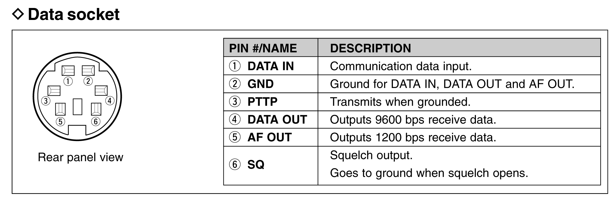
Don’t use the ACC 13 pin connector – Use the 6 pin Mini DIN on the radio instead
By using this method, the MIC doesn’t remain in a ‘HOT’ state. As follows.
Wire the internal SignaLink JP1 Jumpers as below
THINGS TO DO FIRST:
Get a 1m length of Cat 5-e or Cat 6 network cable.
Cut off one of the RJ45 plugs and discard it. The remaining one goes to the SignaLink USB.
The bare wires [there are only 4 that are required] will need to be wired to your 6 pin Mini DIN.
Wire as below and plug this into the back of the IC-706MKIIG
Wrap one end through any ferrite core to kill any stray RF – do 3 turns at least.
WIRING and RADIO:
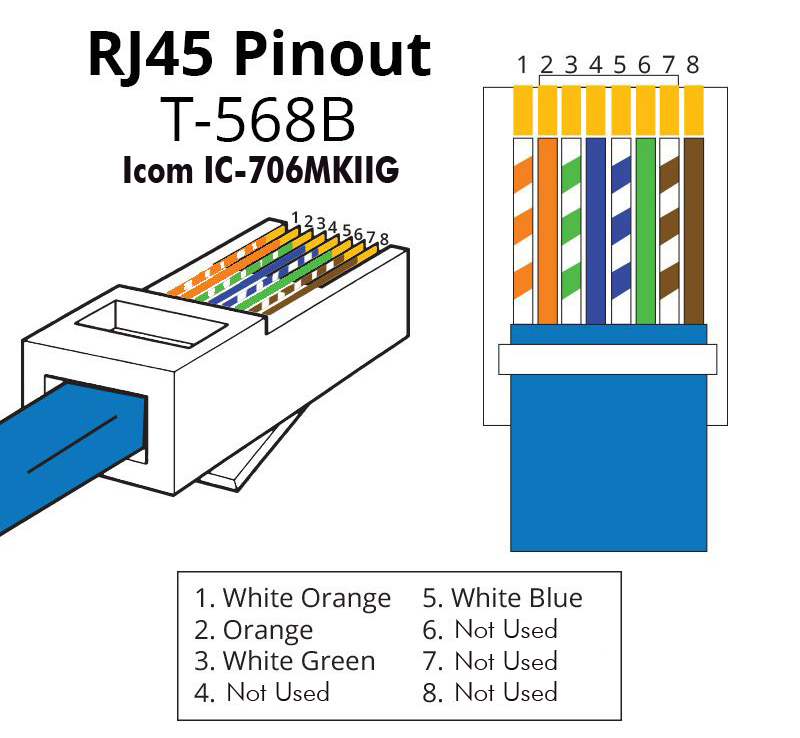
The remaining RJ45 plug goes into the SignaLink rear connector.
- The wires at the far end where the RJ45 plug was cut off go as follows:
- RJ45 Pin 1: Soundcard TX Audio from the SignaLink [White/Orange] goes to Mini DIN Pin 1
- RJ45 Pin 2: Ground [Orange] goes to Mini DIN Pin 2
- RJ45 Pin 3: PTT Keying [White/Green] goes to Mini DIN Pin 3
- RJ45 Pin 5: RX Audio from the 706 to the SignaLink [White/Blue] goes to Mini DIN Pin 5
- Make sure Menu number 29 on the 706 is set to ‘1200’ and NOT ‘9600’
SUMMARY:
There’s some [limited] online info regarding this problem, but Tigertronics reported that the issue is with the radio (and not the SignaLink unit) and is caused by a lack of isolation between the radio’s Mic and Accessory ‘ACC’ jack. Normally the ACC Port is fully isolated from the mic jack and whatever you attach there will not affect the Mic audio. However, on some 706 radios, they seem to be lacking in isolation and the ACC Port loads down the Mic circuitry which results in weak Mic audio until you turn up the Mic gain.
I tried turning up the mic gain to full and also putting a resistor across the mic jumpers on JP1 as another suggestion but neither of these methods worked.
Go down the 6 pin DIN plug route, but make sure you also hook-up the additional ‘RX’ audio lead from the rear of the IC706MK”G to the ‘SPKR’ input of the Signalink unit and all should work fine.
With this setup, I’ve managed to work plenty of FT8 and even have 3Y0K [Bouvet] on a handful of bands with just radio power.
GL, very 73 Steve – G0UIH

