
Here’s the final video in the Command Technologies HF-2500 teardown and rebuild by Steve G0UIH – Vortex Antenna Systems/Q82.uk. Here in Part 8, we summarise on what’s happened during the rebuild and test the amp basic operation using a low power [9w] input from the IC706MK2G – just to test for basic operation.
See the Video Part 8 – Summary and Testing
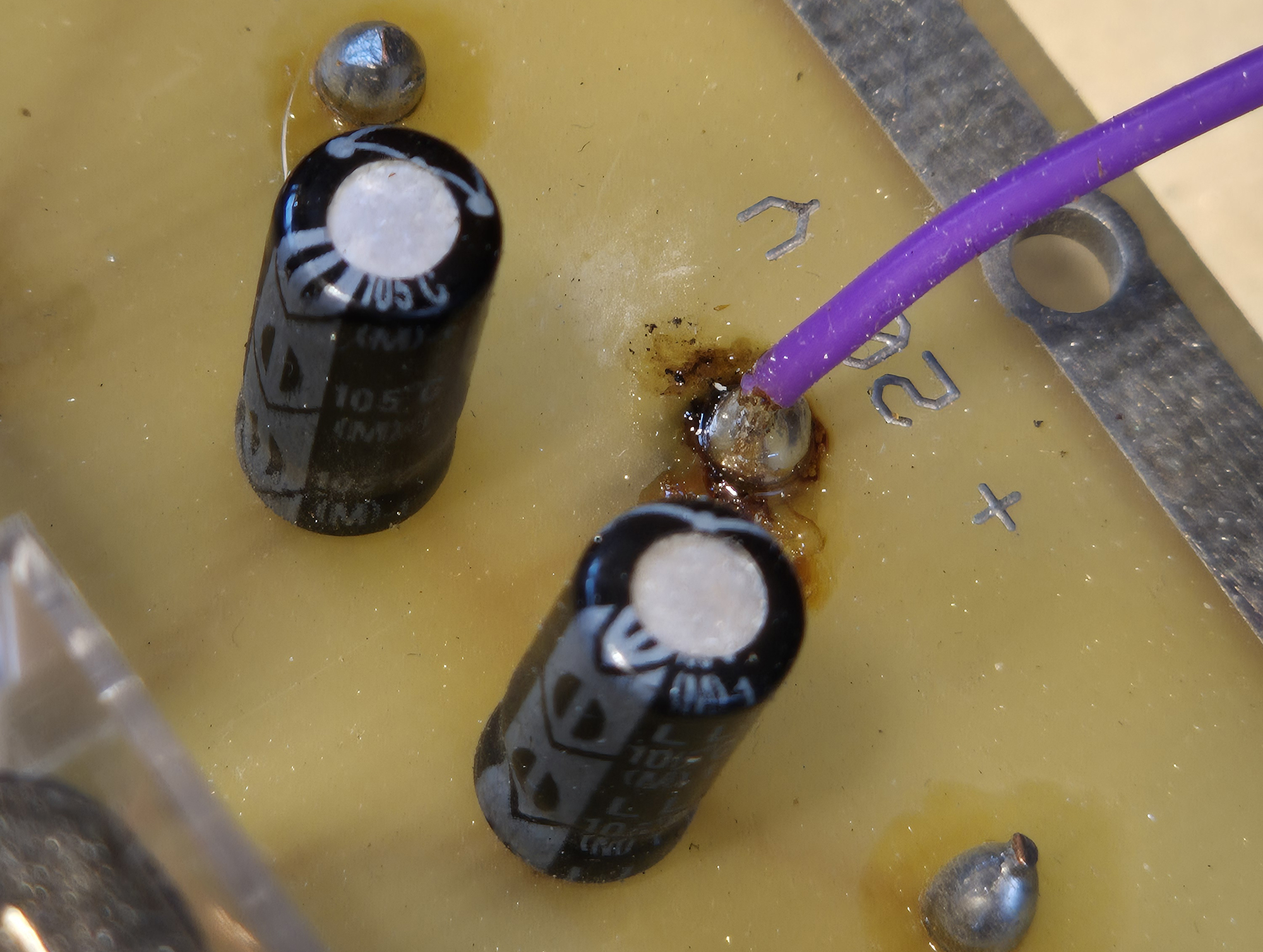
The Purple/Violet Lead Error:
As mentioned in the video. When you re-solder the violet wire to the relay PCB, the wire should go FULLY through the hole. The actual solder side which powers the relays is the bottom side of the board. This is the side that faces DOWNWARDS. Make sure the wire is soldered on this side.
Click on any of the images below for a larger hi-res version.
This is the bottom side of the board. Make sure any solder work here is good.
Measuring continuity between the top of the violet wire [+V input] and the bottom of the PCB
which is the input to the board. OPEN CIRCUIT!! – no wonder the relays don’t key.
This is the top side of the board. The solder join here does nothing. The top pad is actually floating!!
This is the bottom side of the board. Make sure any solder work here is good.
This is the pad that supplies +V to the PCB
New Capacitors in the High Voltage PSU:
When I first purchased my HF-2500 new back in 2006, the plate voltage read about 2700v. With the better electrolytics in the PSU, this now reads just under 3000v. I notice some sag when transmitting, with the voltage dropping to around 2850. This is nothing to be overly worried about though. Normally there’s a certain amount of drop when the unit is under load.
Tuning – Just small changes seen:
I have my old band selection tune/load ‘crib sheet’ which I used to follow when tuning up the amp. I now find that the ‘Tune’ capacitor now needs a slight re-tune. In general it’s about 4 units [lower] than before with the ‘Load’ being roughly the same.
For instance; the 10m setting used to be Tune 29 and Load 15. Now it’s Tune 25 and Load 16. This maybe due to the PSU supplying slightly more voltage and also an extra 2cm section of copper bar used just to set the tank coil further rearwards. No other lead lengths were changed in any way. I found similar small changes on 15/17 and 20m.
I’ve not tried the lower bands as yet.

