Antenna Modelling Software Shootout:
EZNEC Pro/2+ vs AN-SOF V7.0
OK, here’s a pretty heavy-weight contest. EZNEC Pro/2+ from Roy Lewallen’s W7EL stable and AN-SOF V7.0 from Golden Engineering.
As an EZNEC paid up user for many years, I was [very] interested from the continued development by Golden Engineering’s AN-SOF antenna simulation program especially as EZNEC’s owner W7EL had officially retired at the end of 2021. So I purchased an AN-SOF license and got to work on a new learning curve.
Whilst others may either shun some modelling programs [remember ‘Antenna Amplifiers’ controversial and infamous statement saying that EZNEC was for ‘Amateurs’ and not ‘Professionals’], EZNEC Pro/4 led the way for many years.
This has subsequently been removed and replaced by ‘Antennas are designed with professional full 3D EM modelling software’ – so a change of heart for sure and maybe they were taking quite a bit of flak.
Anyway, we’re here to evaluate two packages and not to get involved in politics. The idea being that we will model a design in both EZNEC Pro/2+ and AN-SOF V7.0 then perform a live build and determine the results, feeding what we found back to you.
It’s then up to each individual to determine whether they find either of the applications useful.
Background:
EZNEC from Roy Lewallen ‘W7EL’ has been one of the favourites for many years now – especially in the ‘ham’ community. Roy developed the various NEC formats into a user-friendly package and over the years this has progressed into V7.0. I like the UI – it’s great and easy to use. It uses either an ‘NEC2’ or ‘NEC4’ calculating engine. The latter being perceived as more accurate and can be used only after an issue of a license from the Lawrence Livermore National Laboratory in US.
The current license is NEC5. I’ve used EZNEC for many years and find it an easy-to-use intuitive package. Today, EZNEC Pro/2+ is freeware and can be downloaded at no cost from W7EL’s website. EZNEC Pro/4 license holders can also download EZNEC Pro/4+ when they enter their correct licensing details.
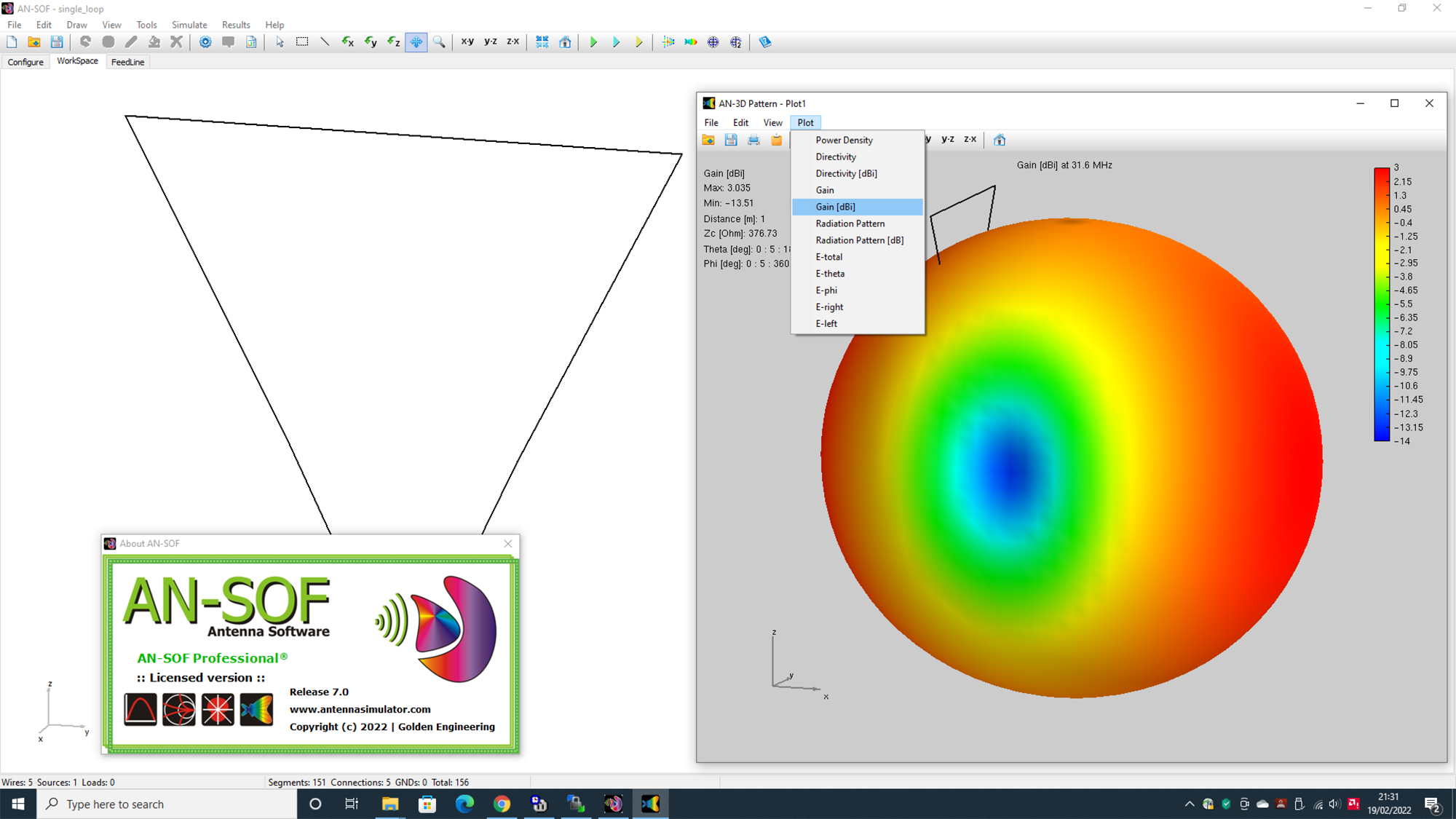
AN-SOF from Golden Engineering is a different proposition and in ‘Ham’ circles – a new kid on the block. It’s very different to EZNEC and I must admit as an EZNEC user, found it a bit clunky to get used to. Some of the EZNEC functions are ‘multi-functions’ in AN-SOF so not as straightforward. However, when I did get my head around it, I found it a very accurate tool to use. It uses the ‘MOM’ [Method of Moments] algorithms which are not associated with the NEC calculating engine and touted as being much more accurate. It’s a new 20th century environment based heavily around 3D computer modelling.
AN-SOF is a subscription service. Costs are based around various subscription offers, so unlike EZNEC – it’s not free.
I’m aware of EZNEC limitations as already discussed here on Q82.uk and I’m looking forward to put both packages to a real-world test.
This evaluation is based on two parts. We’ll built the computer model and then show the model in both packages. The EZNEC version will show an EZNEC format file [.ez] and we will then import that file into a converted ‘NEC’ file for AN-SOF. After this we’ll compare each model with the actual ‘live build‘.
AN-SOF allows the import of both NEC and EZNEC file formats. Bar a line of additional text that EZNEC produces at the end of the file that we need to remove, the NEC file conversion is purely ‘text’ so no ‘changes’ as such happen. It’s an ‘apples-to-apples’ comparison.
Following each model, we’ll build a real-life version of the antenna. In order for simplicity, I’m going to build a single delta loop antenna. No point in building a multiple loop or multiple element antenna if ‘one’ single element isn’t right!
A couple of reasons for choosing the loop. Firstly, that’s what I’ve been building for many years. When ‘Vortex’ was trading, the ‘Delta Loop’ was at the heart of what I built and I’ve built a few [hundred]!
Secondly, loop antennas often showed the limitations of what EZNEC was capable of. Things like ‘Stepped Diameter Correction’ and ‘Wires at Acute Angles’ were the main areas of contention especially when using the NEC2 engine. I’ve lost count of the times users emailed me with EZNEC models that failed to work as expected in the ‘real-world’. So, we’re out to get to the bottom of this conundrum once and for all. What is really going on and is EZNEC that bad at modelling some designs [Loops for instance]?
Model and Build info:
The above information is based on modelling and an actual built antenna. The results we have experienced are based on a physically built antenna which represents both a free-space and a ground potential of average ground. All models are at the correct height above ground and model the actual wire materials. We changed the ground to model both a ‘poorer’ and ‘better’ ground. In essence, it made no real perceivable difference in this experiment.
Modelling:
In each model, the live build was built EXACTLY as per the model. No shortcuts. Tubes were the correct diameter and lengths doubled checked as being the same as in the model. The top wires were 2mm bare copper wire. We didn’t use ‘PVC’ or any coated wires as this [could and would] change the velocity factor of the wire and potentially introduce errors into the equation. The idea is to model as simply as possible with the minimum of potential errors.
We were overly generous with segmentation, using 10 segments per meter of tube/wire so giving each application plenty of data to chew through.
The antenna was not matched and no matching devices used. We hooked up the analyser right at the feed point with crocodile clips without any additional wire lengths and took a reading of the ‘best-dip’. As an additional test, we did the same with a 1:1 choke balun with a type 52 ferrite directly at the feed point to make sure any part of the feeder was not radiating and contributing to the results.
Conclusion:
Given all of the above modelling, data and live build – we feel the following is a fair and accurate representation and round-up of what we found in a ‘real-life’ scenario. In all tests, the choke balun at the feed point made no perceivable [2-3 ohms at most] difference to the SWR curves and resonant point.
EZNEC:
The model showed a resonant frequency of around 32.950MHz based on the antenna at 2m above average ground. A similar plot was run in free-space. The difference was within 150Khz so was not considered a real issue. When the actual antenna was built, the resonant frequency was actually 1.4MHz lower [31.550MHz] than the computed model. The model had 2 vertical aluminium 6061-T6 tubes [16 and 12mm] which were included in the data. The top wire was 2mm bare copper wire with no insulation.
We were surprised on how far the model [compared to the real build] was out. You could take into account some minor capacitance of the green polypropylene ‘Stauff’ clamp into account. But not 1.4Mhz – something is not right.
[All images are ‘clickable’ to view higher-res versions]
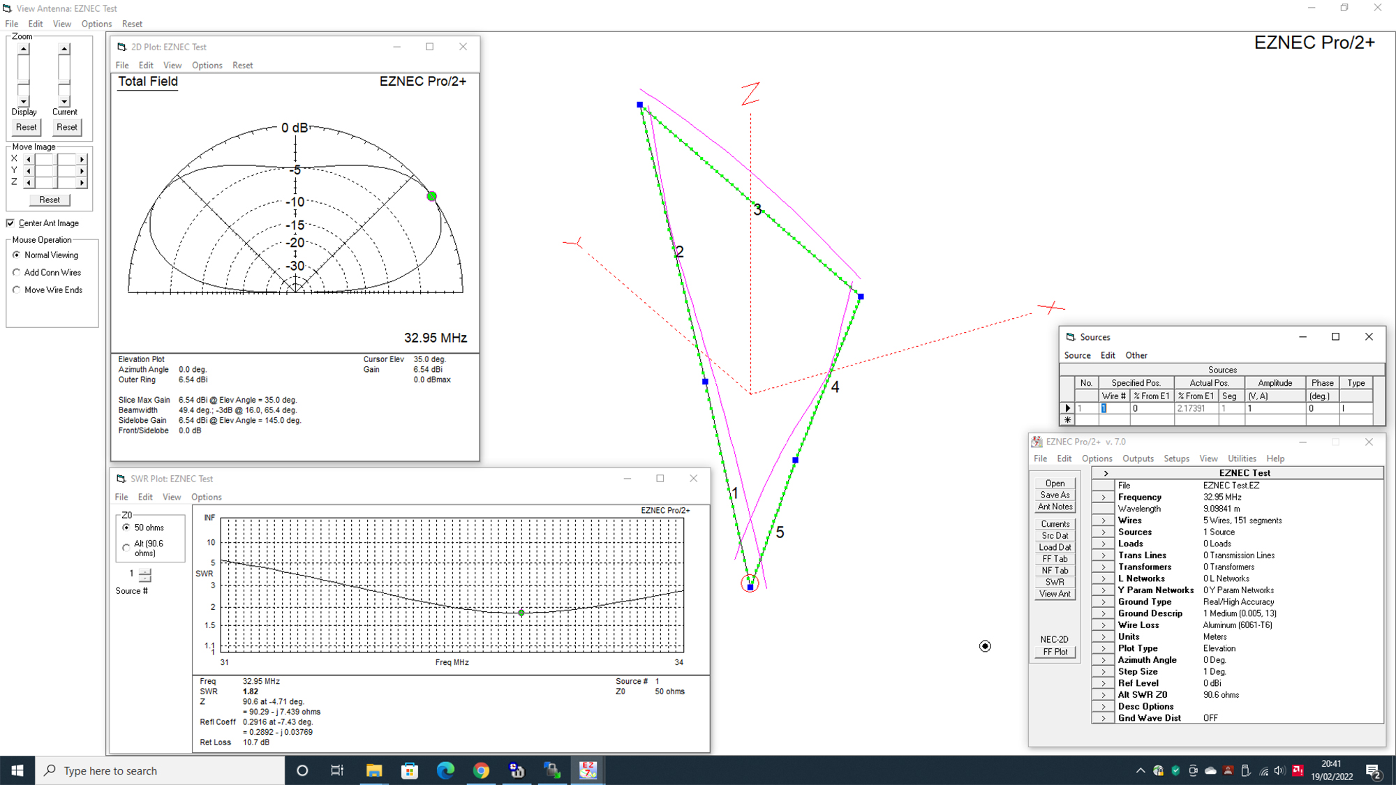
In the past, we’ve frequently struggled with the accuracy of EZNEC when modelling loop antennas.
AN-SOF:
The model showed a resonant frequency of around 31.600MHz based on the antenna at 2m above average ground. A similar plot was run in free-space. Again, the difference was within 150Khz so was not considered a real issue. When the actual antenna was built, the resonant frequency [31.550MHz] was pretty well bang on the nose when compared to the computed model. See below. The model had two vertical aluminium 6061-T6 tubes [16 and 12mm] which were included in the data. The top wire was 2mm bare copper wire with no insulation. Given the plot, the built unit resembled the model with superb accuracy.
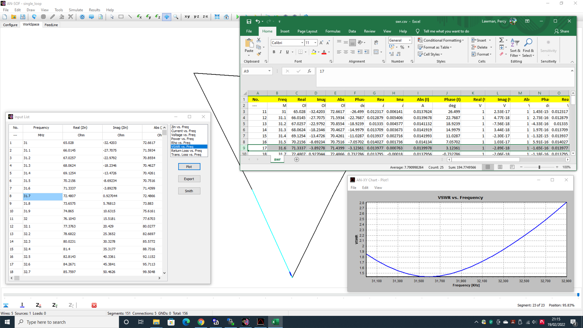
This is superb accuracy – you’d be pushed to get accuracy any closer in any package
Our closing thoughts:
The live builds certainly gave us a larger insight into the dark world of antenna modelling. Whilst we love EZNEC, it’s very apparent that the modelling capabilities are stretched, especially when modelling loop antennas and with the NEC2 calculating engine.
We’ve shown that models are not particularly accurate. A 1.4MHz or so ‘disparity’ based on a loop modelled just above the 10m band is far from accurate. It’s actually a long way out. In defence, I’ve always found EZNEC to be closer when it comes to modelling Yagis. Maybe it’s the ‘Stepped Diameter Correction’ or ‘Wires at Acute Angles’ thing but EZNEC and Loops just don’t seem to get on.
We can’t say why this and it’s beyond what we’re evaluating in this article. It’s actually down to you the end user to decide whether or not this package will deliver what you expect. In summary, and as EZNEC is now ‘freeware’ you’ve no real comeback either way. It’s a free package to use as you feel fit. No guarantee. No money back. If you can make it work – then it’s [No] money well spent 😊
Summarising on AN-SOF. I’ll admit I really don’t like some of the clunky ways to get the data. Certain parts of AN-SOF require multiple ‘actions’ and steps to get the finalised data. I found some of it tedious where EZNEZ was just that – just ‘EEEZEE’.
AN-SOF however [eventually] returned highly accurate data although even if often took a longer time to get to that position.
If you’re happy to learn AN-SOF [and for ex-EZNEC users] is probably worse than being a new user, then it’s worth it. Don’t expect to find items and menus where you think they are. My advice is just forget the EZNEC structure and start and think a fresh.
Saying that, the interface is a new colourful 3D take on modelling. There’s many new menus and items that EZNEC users will get lost in, but the technical support I must say is first class and the helpdesk will often reply back to you [and very quickly] with good ‘how-too’ screen grabs showing you the steps.
If you’re looking to build accurate loop antennas, then AN-SOF is a serious contender. It also seems to alleviate all the ‘faff’ with getting an EZNEC2 model to work, although as you can see on the site, we’ve given constructors all the info we have on how to [successfully] do this.
In essence and in our opinion, it’s the accuracy that counts. In today’s modelling arena, AN-SOF is certainly up there with the front runners.
Reviewed by Steve G0UIH using EZNEC Pro/2+ V7.0 and AN-SOF V7.0 in February 2022

