A Wide-banded Lightweight 6 Element OWA Yagi For 10m on a 9.2m Boom
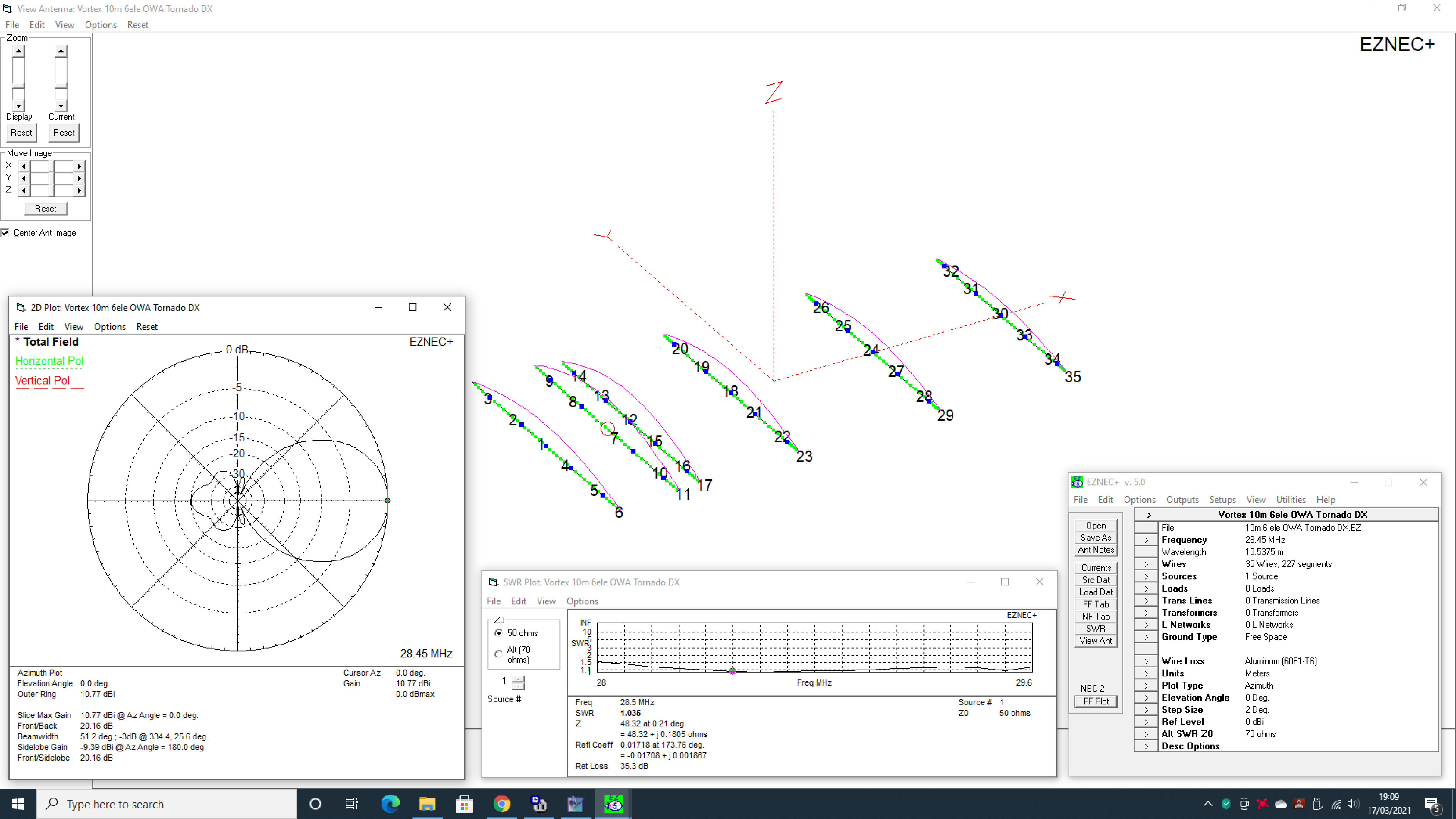
Here’s nice wide-banded 6 element 10m Yagi that gives just under 11dbi forward gain and around 20db front to back – all with a boom length of just over 9m and weighing in at under 20kg.
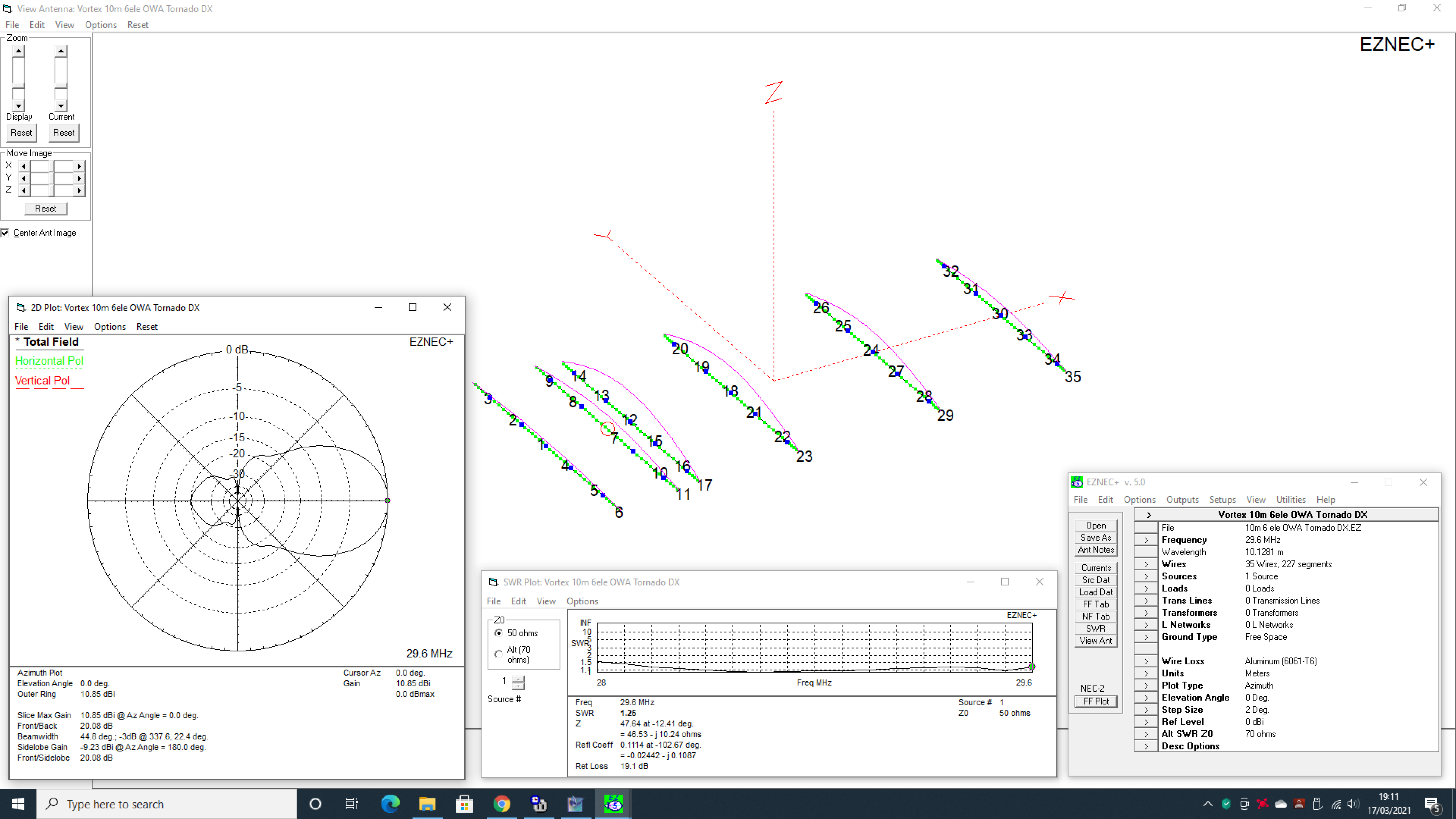
The main criteria for the design was to provide an antenna with a great low SWR from 28.000MHz to 29.700MHz thus giving the constructor full 1.7MHz bandwidth coverage of the 10m band at under an SWR of 1.3:1. We also felt the need to keep the boom fairly manageable. Often you’ll find OWA’s need to be pretty long, especially when trying to hit the magic ‘11.50dbi‘ forward gain point. Here’s we’ve kept the gain just slightly lower and as such makes for a great super lightweight high gain design.
In 2012 I built this one merely as a ‘stop-gap’ antenna as I’d got my sights on other designs. Fast forward 5 years and the design was still in service giving great results. I only took it down because the band conditions on higher HF fell into the doldrums.
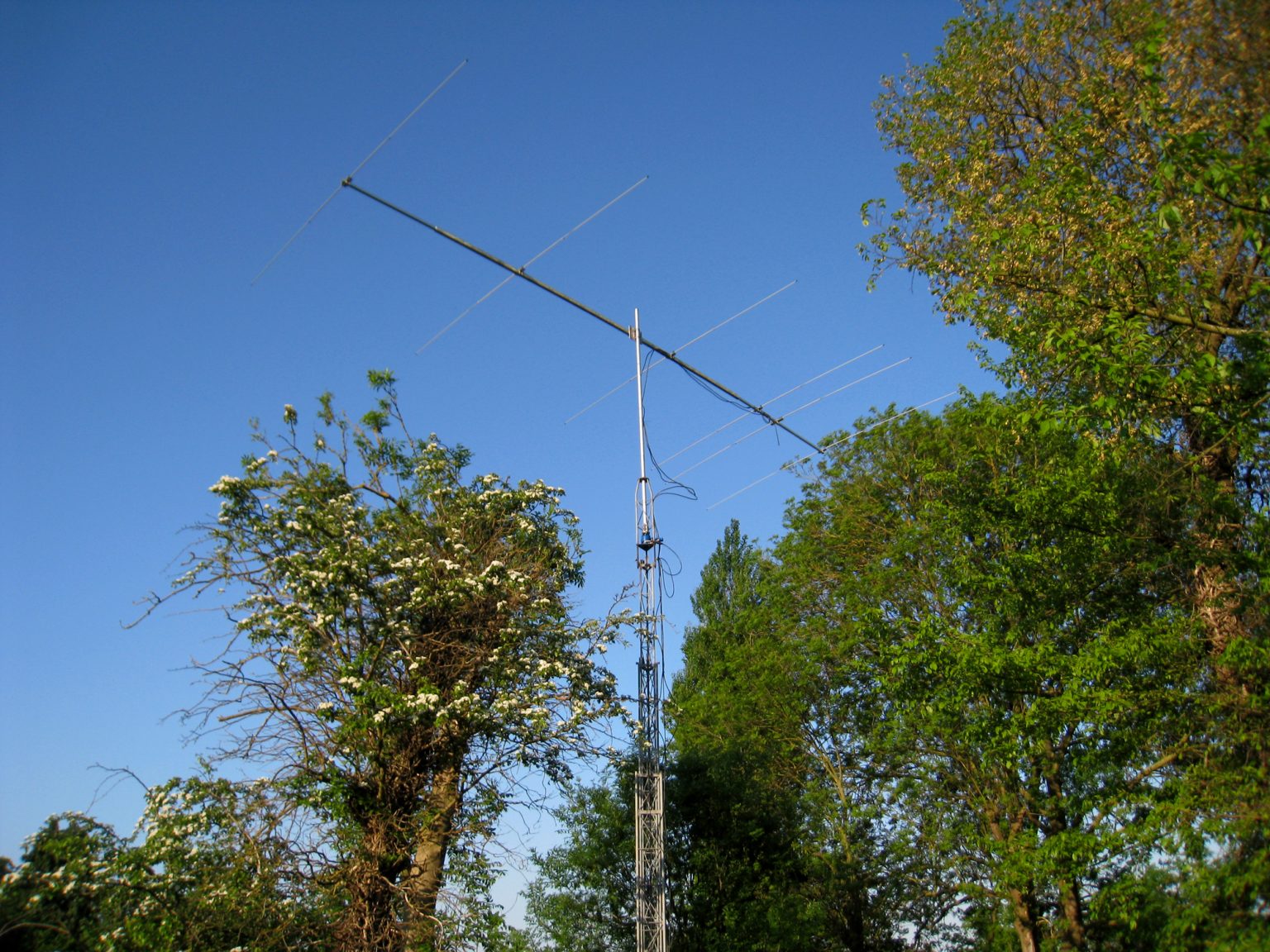
As it was never really intended to be a permanent installation, I built the antenna using some fairly lightweight materials. Well, I thought they’d be too lightweight for the job but that appeared not to be the case.
The main elements are constructed of 6082-T6 5/8ths x 16 gauge tubing which is used for the centre sections with 12mm x 2mm wall outer tubes. These two tubes when combined, actually made a pretty sturdy affair and although we’re not in the most exposed place in the UK – its certainly withstood some battering over five winters. Structurally – it’s as good as the day it was installed.
The boom was a three section affair using a 40 x 40 x 3mm wall 5 meter centre section and two end sections of 1.25 inch x 1.25 inch [31.5mm] x 10 gauge [3.25mm]. There is a small gap when sliding the outer sections in but a couple of M6 bolts held the boom sections well. Purists could potentially sleeve the ends to provide a more ‘snug’ fit. Unfortunately I failed to source any stock of around 34mm in diameter which would have been an ideal fit.
Electrically, the antenna is optimised to provide just under 11dbi forward gain between 28.000MHz and 29.660MHz and this it does very well. Front to back ratio varies from around 17db at the ‘CW’ portion of the band and rises above 20db at around 28.300MHz. From 28.300 all the way up to 29.600, the front to back exceeds 20db and the SWR is virtually flat across the whole 1.6MHz coverage. My own SWR tests showed no more than 1.3 to 1 at band edges so whether you’re a CW, Digi-mode, SSB or FM buff – here’s one antenna that covers the lot!
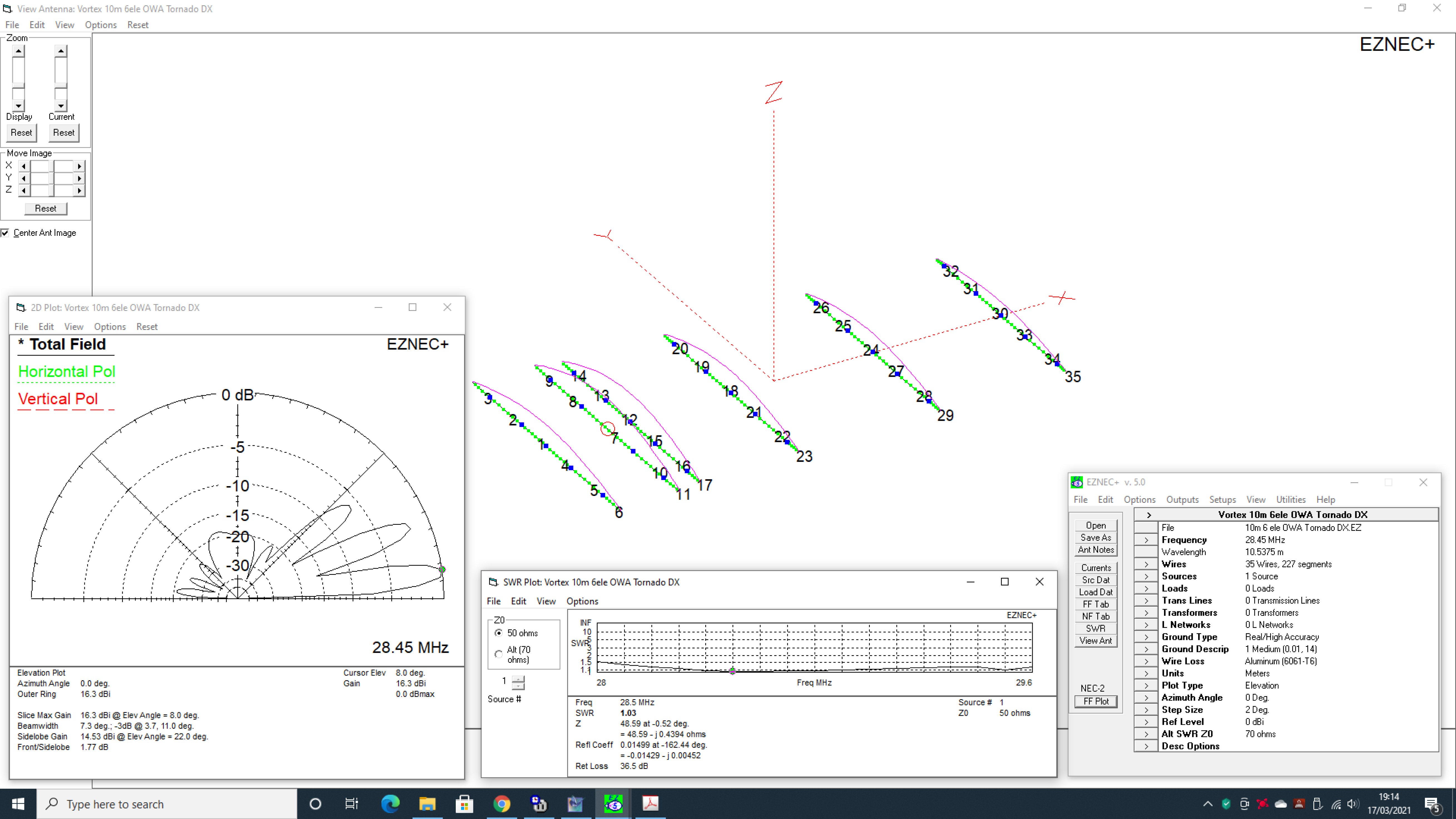
Of course, the great thing about the OWA design is that the natural impedance of the array is around the 50 ohms mark. This means you don’t have to fit any matching device – just a direct feed to a ‘Split-Dipole’ arrangement on the centre part of Wire 7. We would say that a good 1:1 RF Choke Balun [Current Type] should be fitted as a matter of course at the feed-point to reduce any common-mode RF coming back down your coax. See our article here on how to make one for this project.
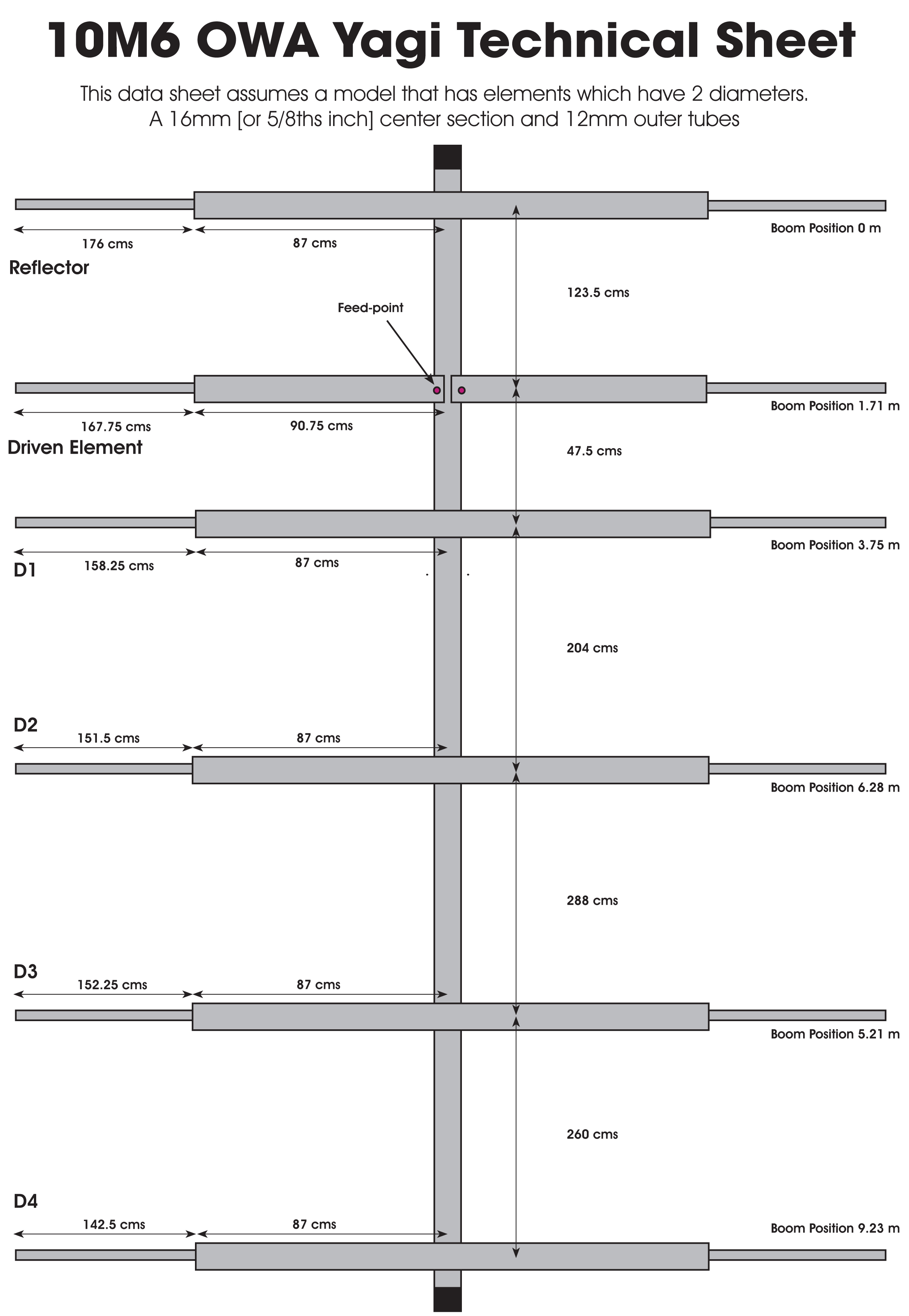
Click on the image below for the PDF download of the data sheet
Download the EZNEC modelling file here.
Constructor Notes Q&A:
Q: Why choose 87 cms x 2 [174 cms] as the total length of the 16mm tube?
A: We had mill supplied sized tubes which suited these cut sizes. Constructors could potentially increase the 20 cm tube to measure 100 cms on each size [and of course reduce the 12mm tubes accordingly] using the same ‘TOTAL’ length without remodelling the array. Minor gain and front to back differences may occur but nothing that would be detrimental to the overall performance..
Q: After assembly and installation, I found a good and wideband SWR curve but it’s slightly ‘High’ or ‘Low’ of 50 ohms
A: We found this too. I put it down to modelling with an NEC2 engine. Those with the luxury [and deep pockets] of modelling with NEC Pro/4 seem to have builds closer to the model. When using EZNEC+ [or Pro/2] and other simulations using NEC2, we’ve found minor discrepancies – but our aim here is not for constructors to shell out over $1000 in software and licenses. Our advice is to tune the array but change the lengths [by 1 cm at a time] of the end tips of NOT JUST THE DRIVER, but also the end tips of the first Director D1. Both elements work in tandem by controlling resonant frequency and the associated impedance. The use of an antenna analyser would be extremely useful and is really a ‘MUST’.
We found by some experimentation and a little ‘graft’ and patience, that we could improve the SWR by a reasonable amount and tune the array by adjusting both elements together. Here, at G0UIH, we had a final SWR figure of below 1.2 to 1 over a 1.5MHz bandwidth rising slowly at the lower band edges, but quickly at the higher end.

