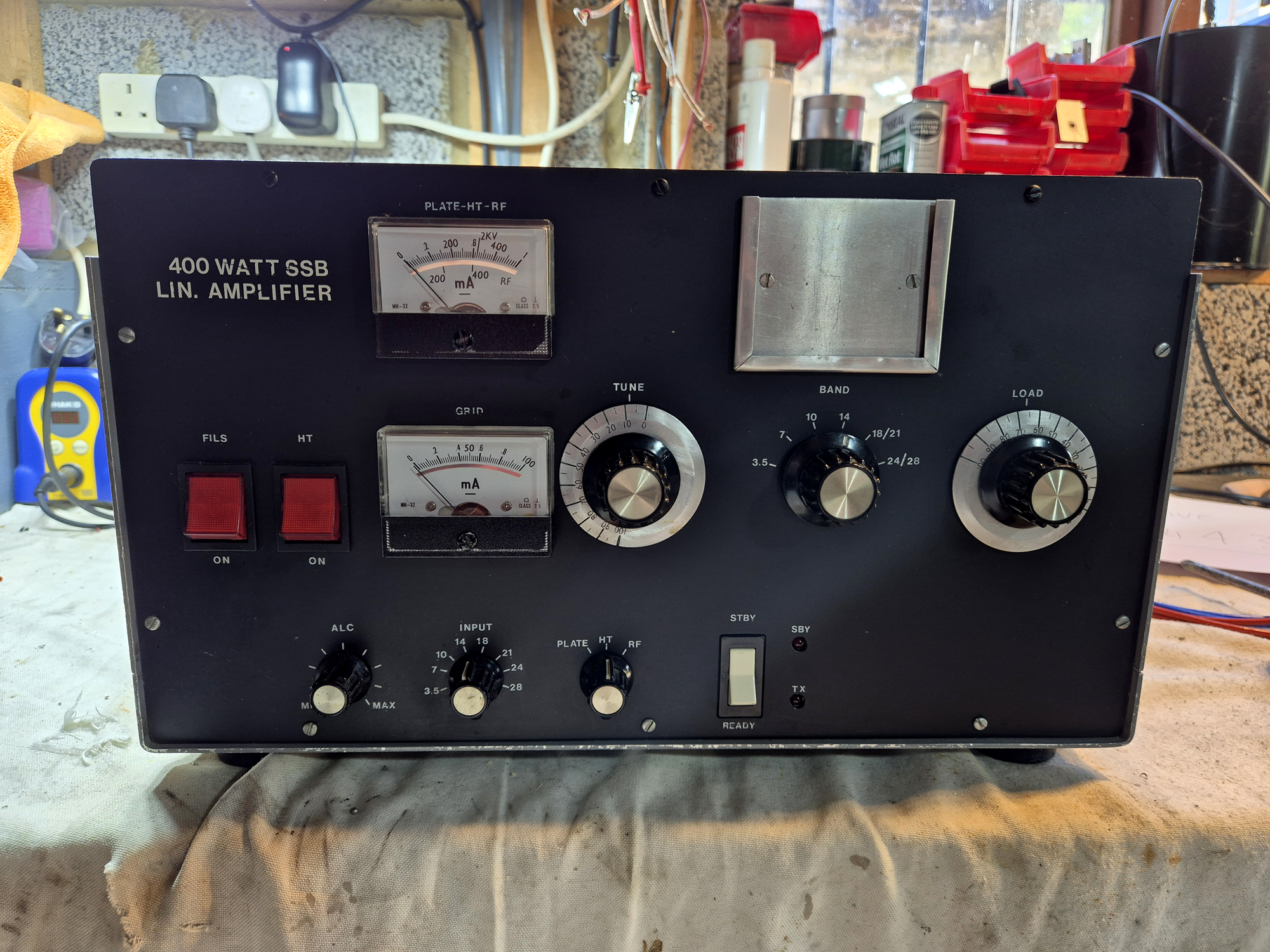
A friend has asked me to rebuild the power supply board in his homebrew 400w amp.
June and July 2026 have been pretty busy months with a couple of antenna builds and some workshop hours. I repaired a friend’s Icom IC-775 DSP and at the same time, he asked me whether I’d check over his homebrew 400w amp. He said the PSU caps looked all bad but he wasn’t keen in poking around in it, given the high voltages inside. Plus he has a pacemaker fitted which wouldn’t bode well if there was an accident.
Click on any of the images for a larger hi-res version.
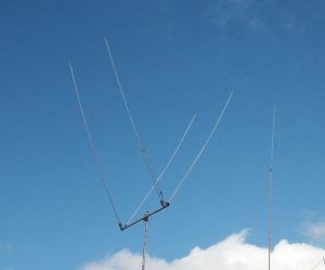
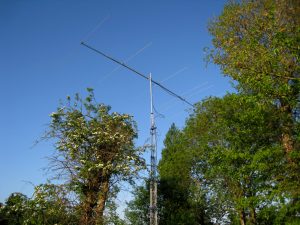
I asked who built it and all he could remember was a guy from Scotland. There’s only one guy I know of over the border and that’s Gordon GM3UCI who is a first class constructor. I built Gordon a multi-element tri-bander, specifically designed to withstand the 100mph winds he gets at his QTH. That was about 15 years and it’s still going strong today.
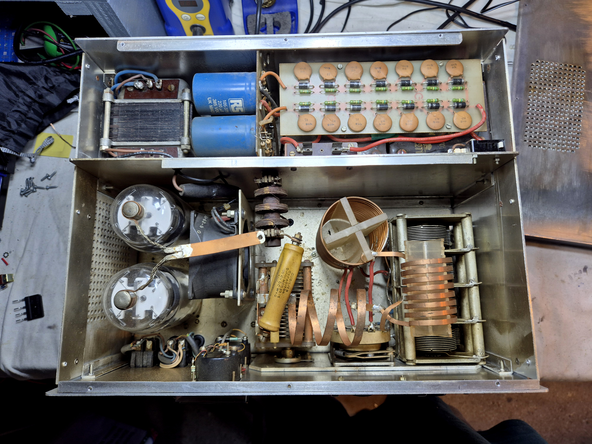
So onto the amp. Lid off and the outputs are 2 x 813 tubes. Pretty classic stuff and the amp should be capable of around 400w, maybe more. There’s separate selection switches for the input and output so individual band tuning which is nice. It covers 80-10m including the WARC bands. The HT meter read around 2kv which is pretty well spot on.
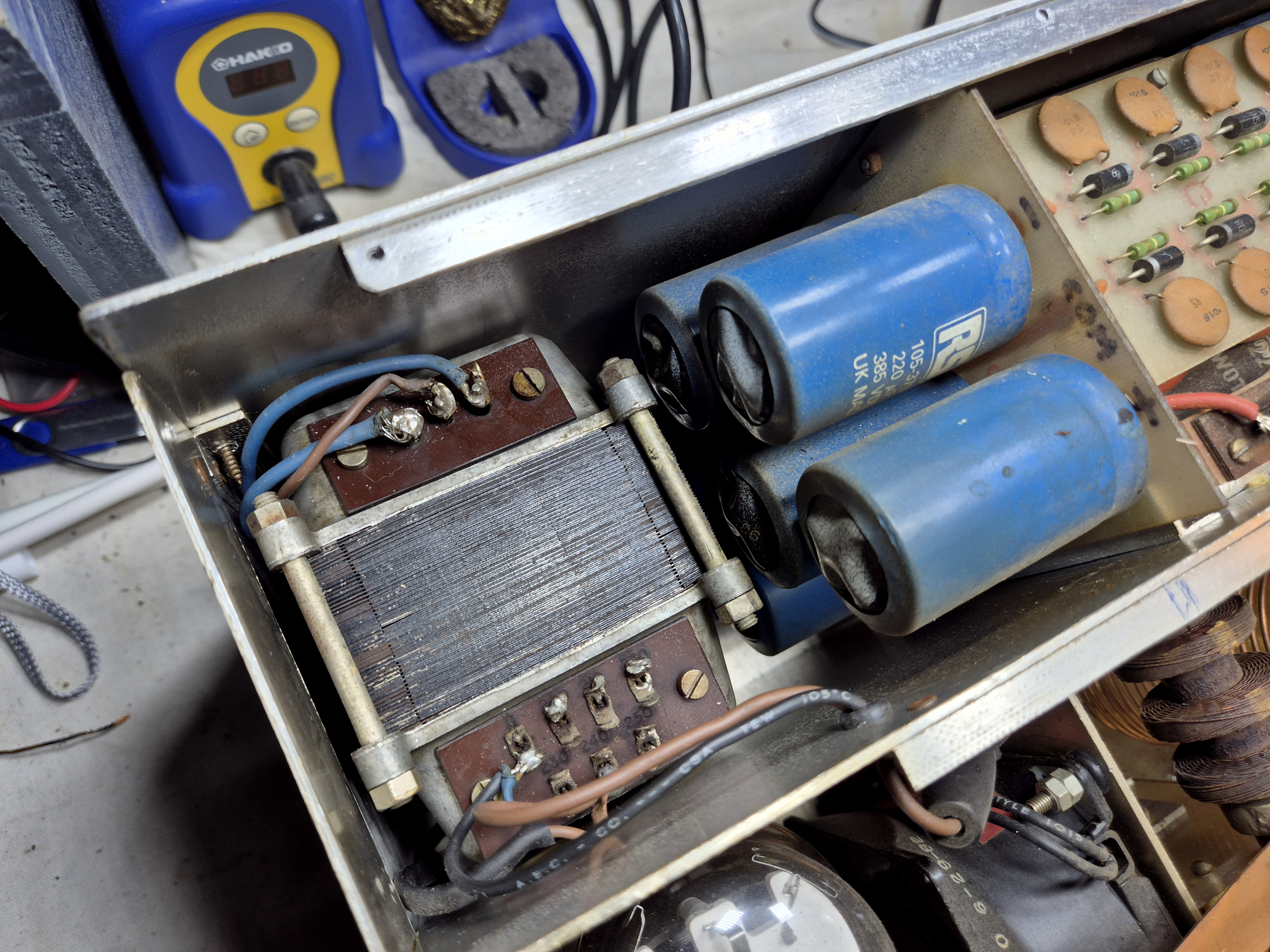
There’s a fitted chassis interlock that turns the HT off when the top cover is removed, so we need to circumvent that when testing. The HT line has a 5 amp fuse fitted which immediately fell apart when I removed it so that needs replacing.
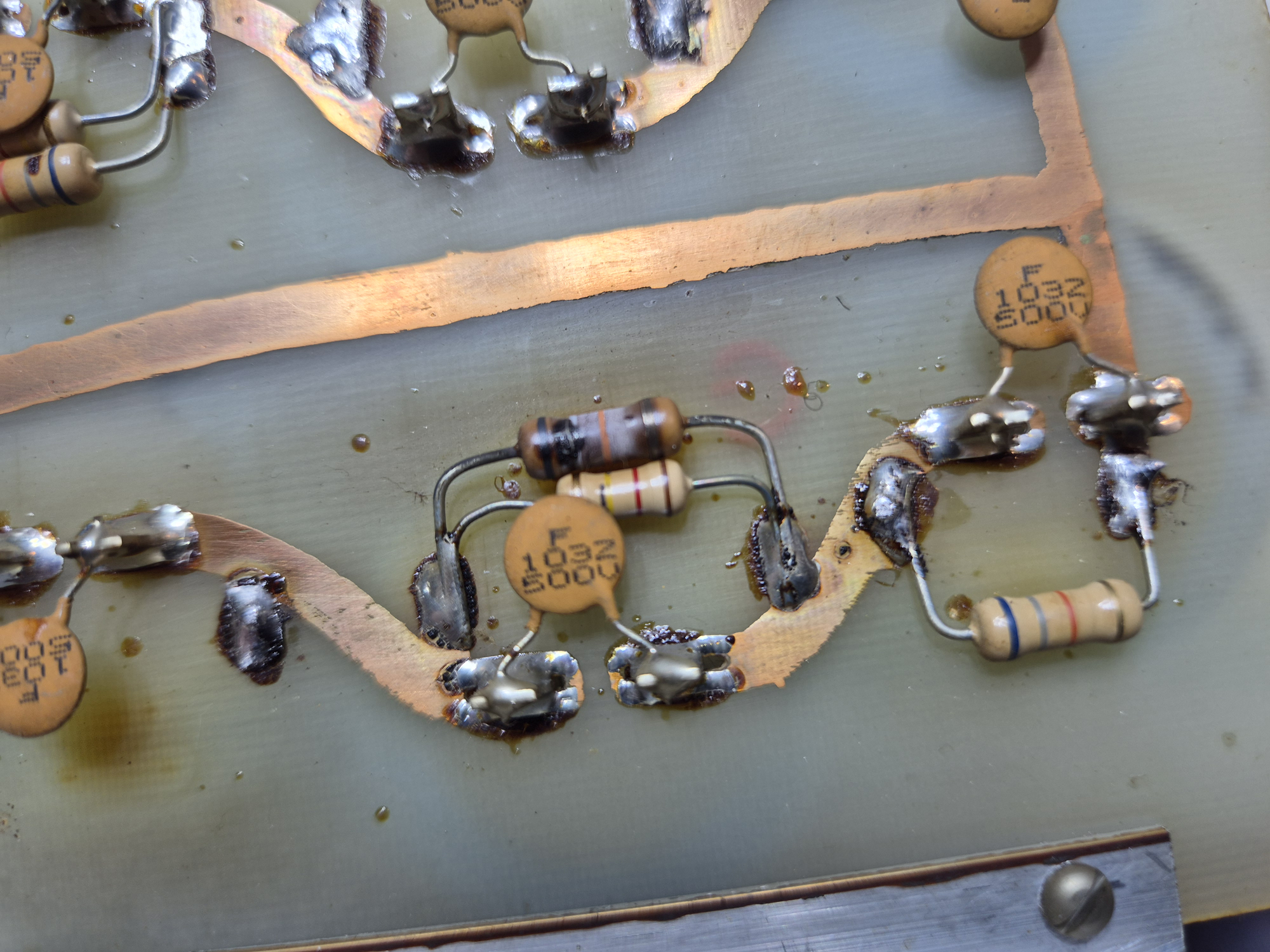
The PSU board has 8 x 220uf 385v caps, originally from RS Components together with capacitor bleed resistors. On inspection, some of the resistors were bad and burned. On checking there was a whole array of varying values including two that were open circuit. The best thing for this was to discard all of them and start again.
Across each capacitor was an 0.01uf 500v ceramic disc capacitor. These caps are used as bypass caps This prevents stray RF from feeding back into the power supply or radiating into other circuit stages, ensuring amplifier stability and preventing parasitic oscillations. They were all pretty old, so as the board is out – time to replace these as well.
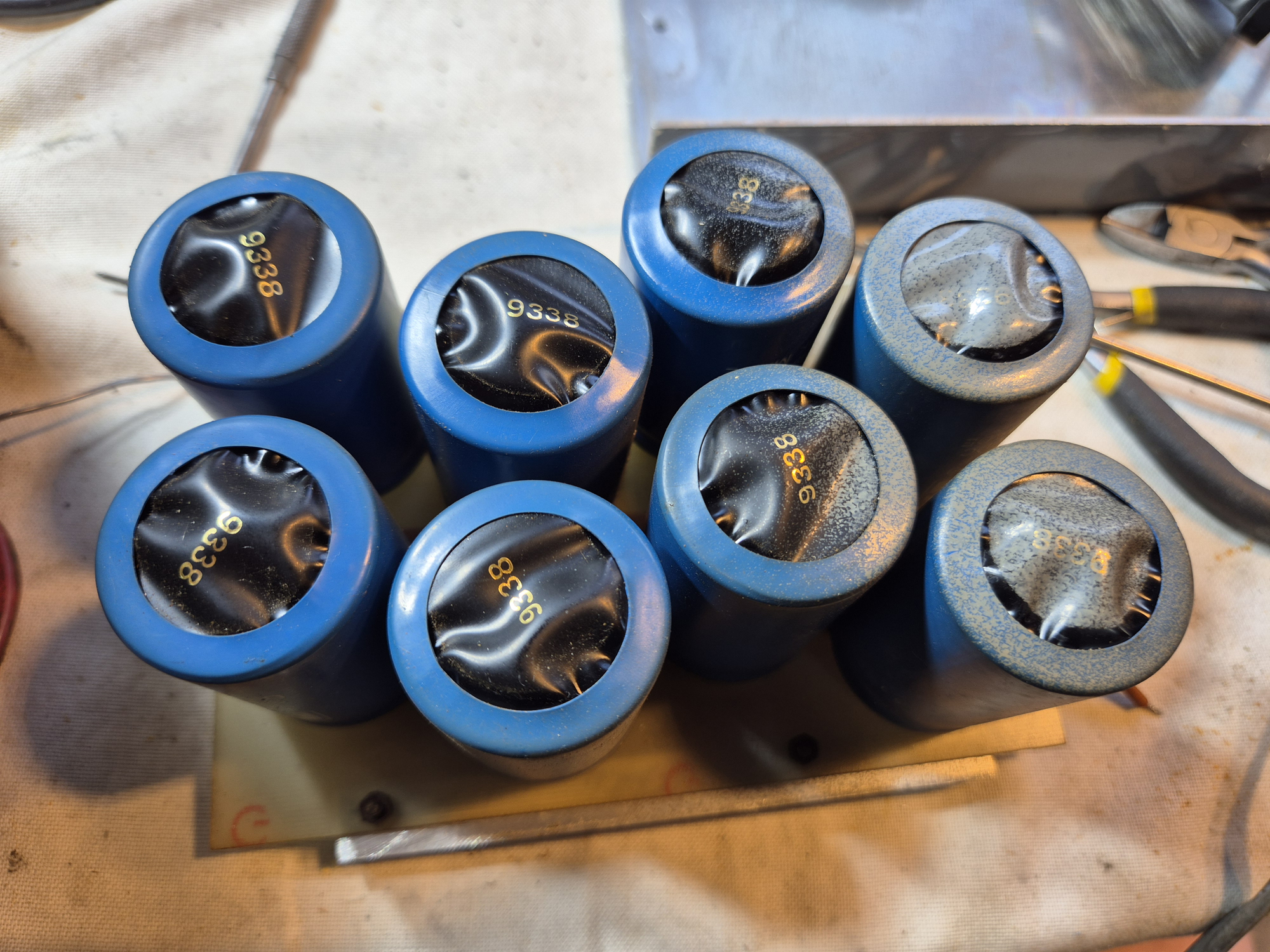
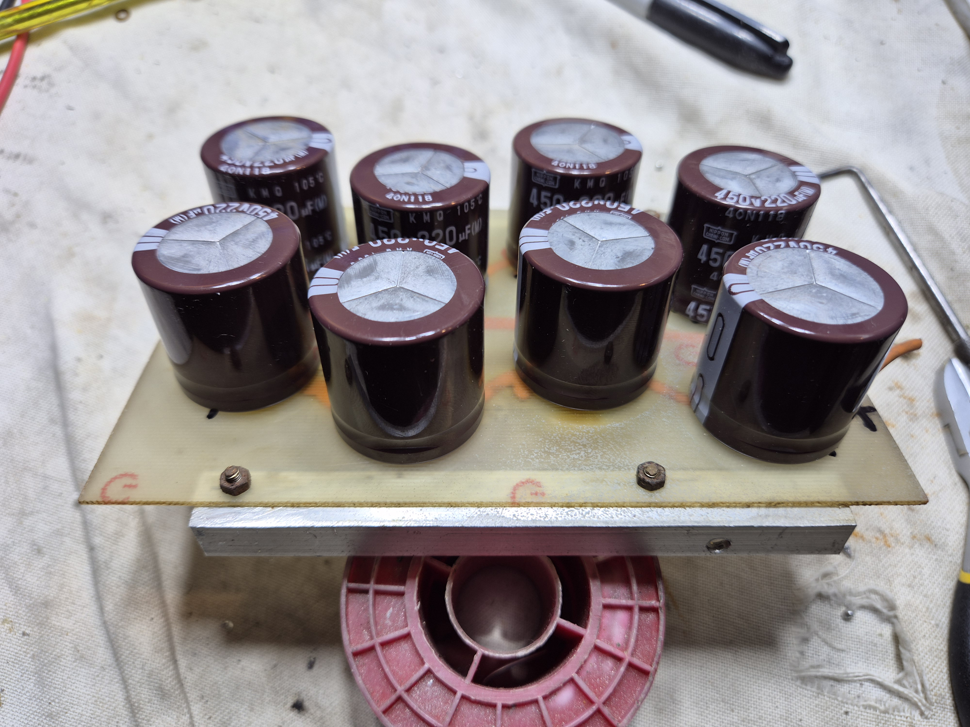
The main electrolytics looked in a pretty sorry state. All had blown tops [very similar in appearance to my Command Technologies HF-2500 board when I disassembled that]. The owner said that he’d already purchased some replacements. These were a better spec at 220uf and 450v working, although the newer replacements were about half the size. It seems technology has improved over the years so a modern equivalent is only about half the size. As long as the voltage value equals or exceeds the original which it did [385v vs 450v] – then we’re all good to go.
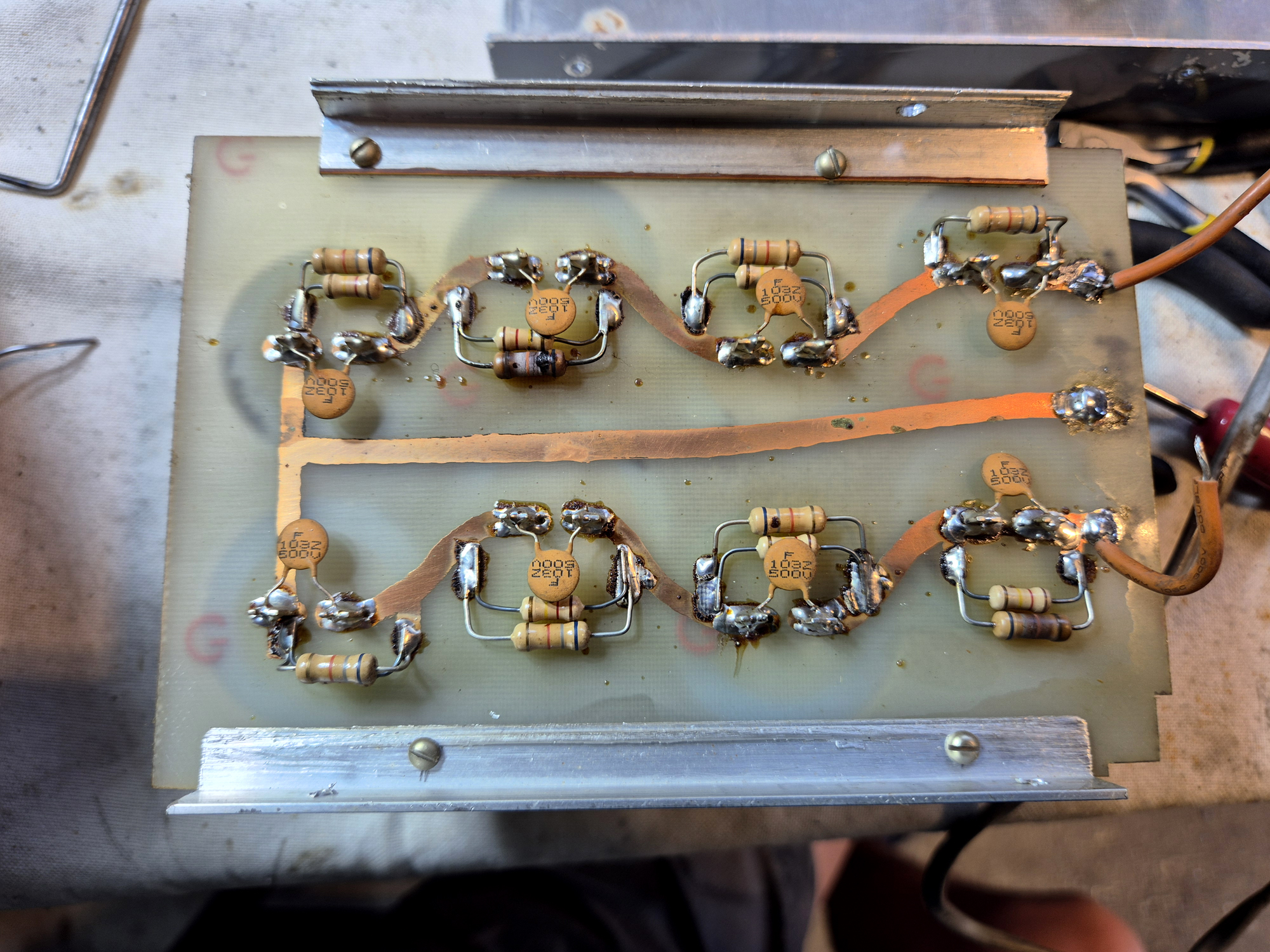
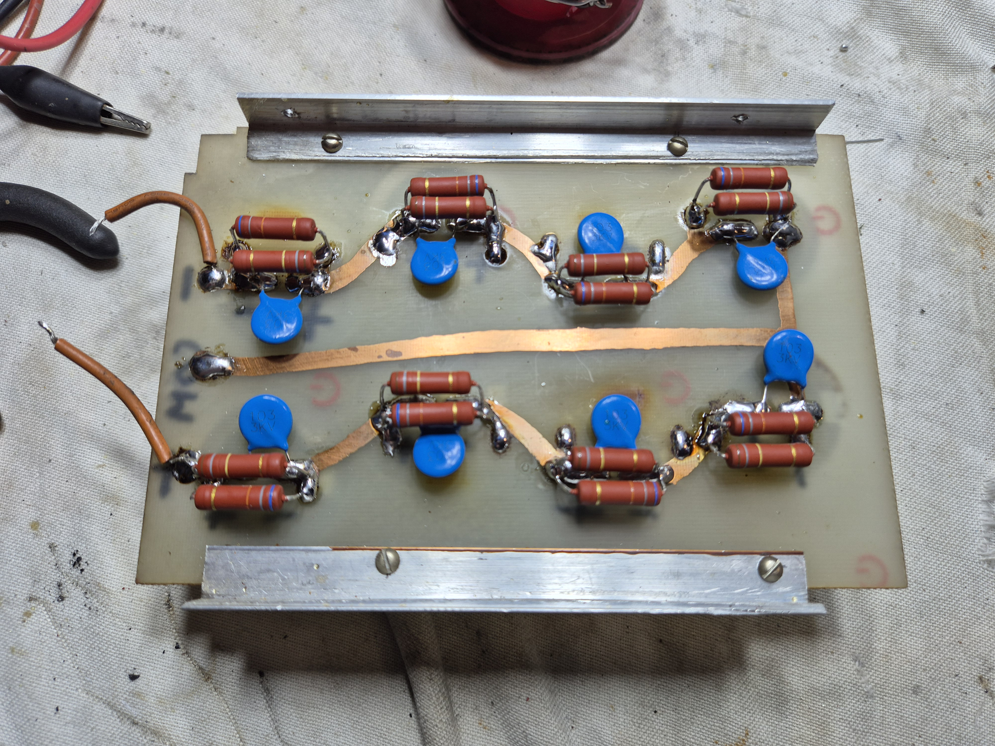
So, here’s the completed and re-assembled HV board. You can see the new ‘Blue’ 0.01uf ceramic bypass capacitors. These have been uprated from 500v to 3kv as a matter of course. I also had plenty of the 3kv versions in the workshop. The new capacitor bleed resistors are now also soldered to the board.
Here we used some Vishay 3w 750v working metal resistors. The old ones were 1w+2w versions paralleled up and probably only 500v working given their age. We’re now using 3w+3w paralleled up so a much better modern alternative with increased voltage and power handling.
Normal tuning for this type of amp is tune for max output and then dip the grids with the load. I found that loading slightly low dipped the grids nicely and retained full output at around 50ma total grid current. A couple of 813’s shouldn’t exceed 60ma for intermittent SSB use, so we’re looking spot on.
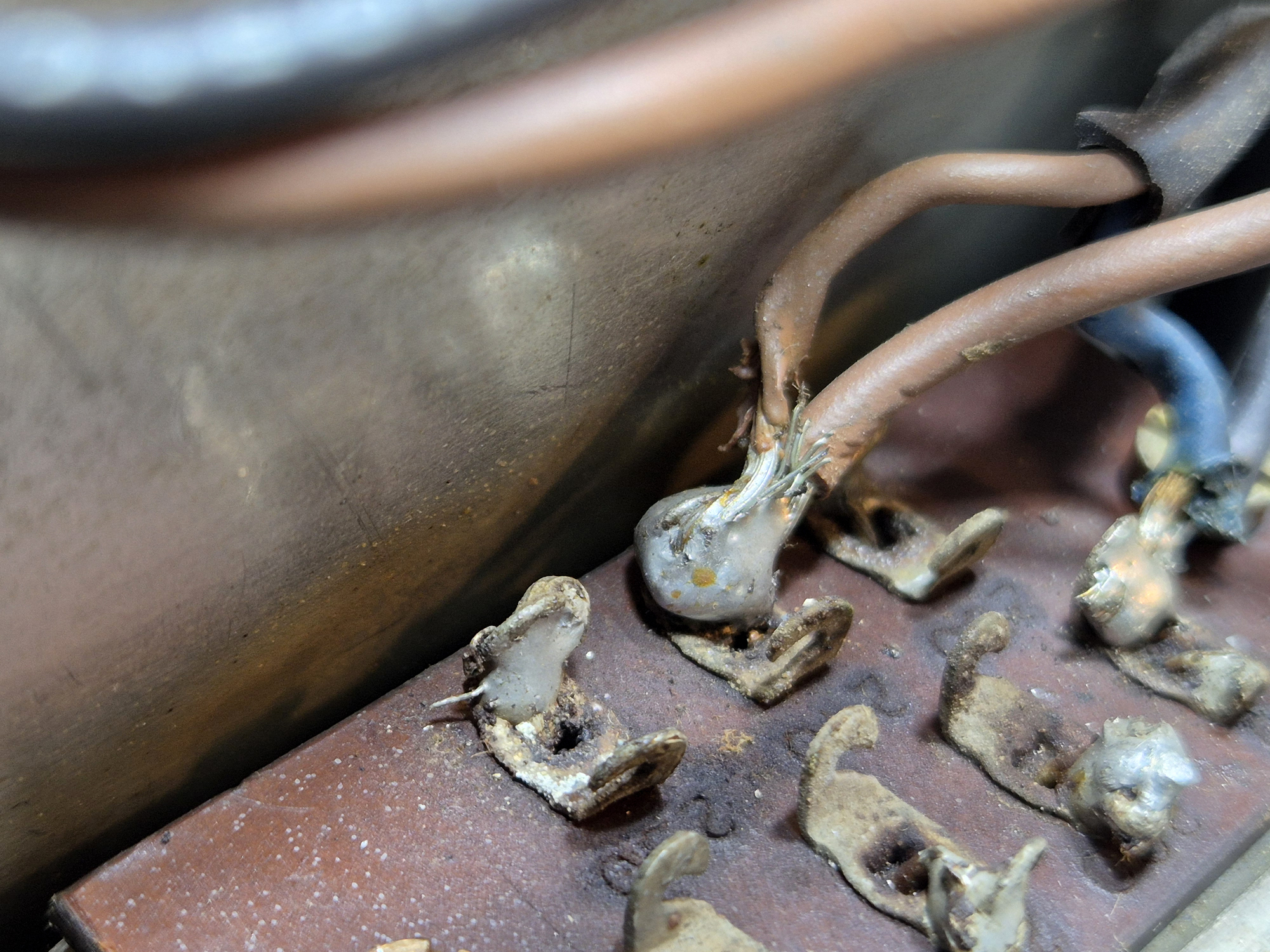
Whilst inspecting, I found this ‘Live’ 240v wire from the transformer sitting very close [within a mm] of the chassis. If that touched the chassis, it could have been an interesting experience. A bit too close for comfort. I unsoldered it and re-routed to around 6mm separation.
In all, a pretty good rebuild. For info, I was also going to replace the cooling fan for the tubes with something a little more suitable as the old one [although it worked] wasn’t in great shape and laboured quite badly.
However, to replace the fan would need the tubes to be removed and I noticed that the anode cap on one tube was lose. The tube still worked, but it wouldn’t take much to break the glass seal on the tube and release the vacuum rendering it useless, so that’s a job for when the tubes need replacing.