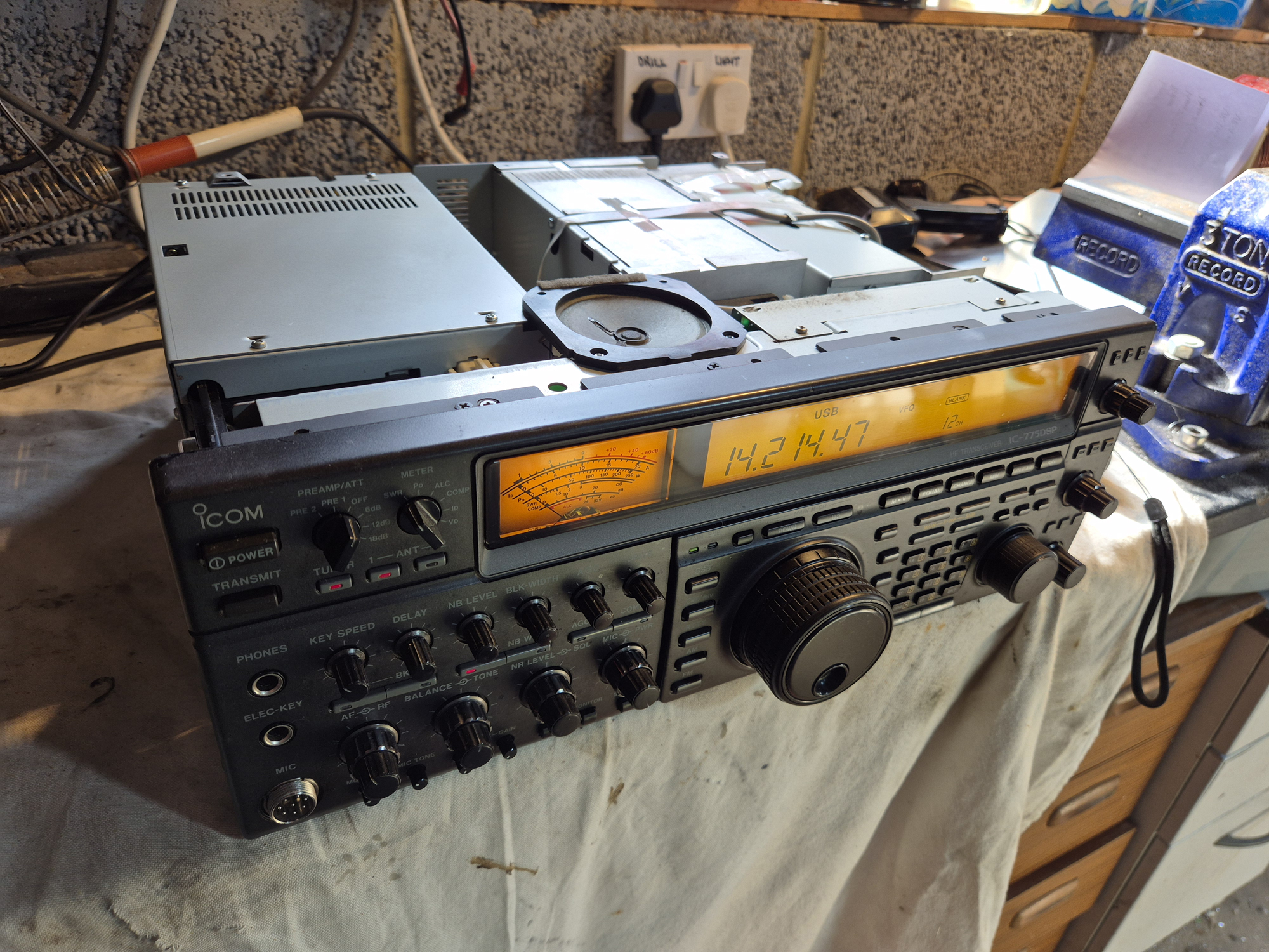
A freind’s Icom IC-775 DSP is dead and won’t switch on. Time to delve in and find out why.
Bench time again. Recently, I delivered a custom antenna to a friend of mine. Whilst at his QTH, he mentioned that his trusty Icom IC-775 DSP was dead and wouldn’t power up. He also said that he’d been waiting for a mate to fix it – that was a year ago.
I offered to take a look but never guaranteed that I could fix it. It wouldn’t take a year, but it depends on what’s gone on and if there’s been any ‘fire’ inside. He said there had been no apparent issues only that one day it just stopped working.
Click on each image for a larger hi-res version.
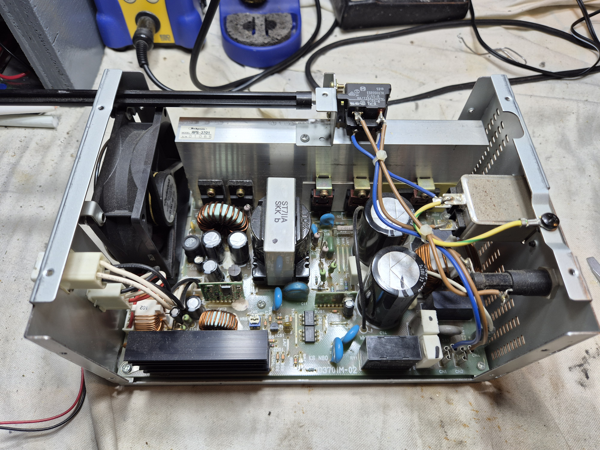
So with the radio on the bench, a switch-on reveals nothing. As mentioned, the rig is 100%.dead so time to trace the power back to see what’s [not] happening. The main 240v AC lead is fine as is the fuse. On the rear of the 775 is a 5 amp ceramic fuse which is on the input side of the SMPS [Switch Mode Power Supply]. If there’s a dead short somewhere, this fuse would be expected to blow but it was good. Something [somewhere] has probably failed ‘Open Circuit’.
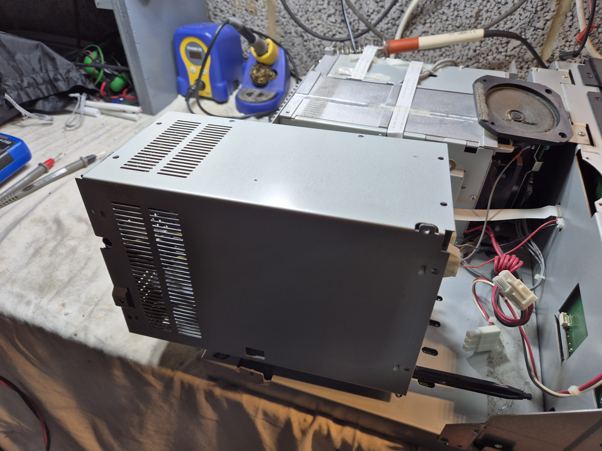
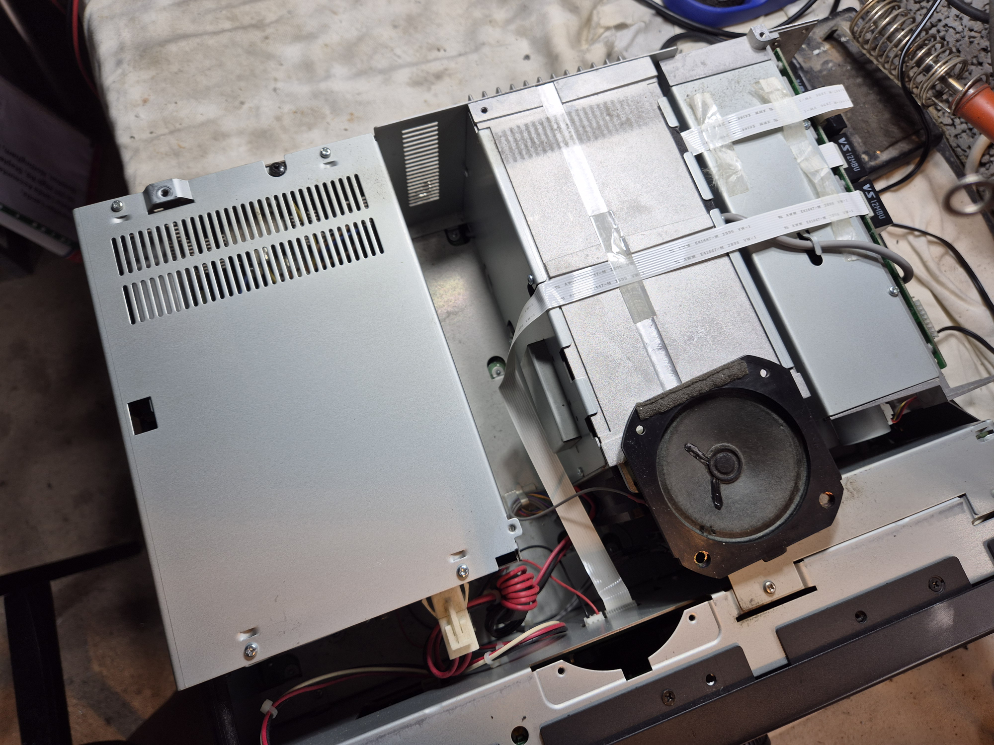
Just unplug 2 leads at the rear and the speaker lead and we’re in business
I decided to see if there were any volts getting to the electrolytic caps, so I carefully put my multimeter on the positive terminal of one cap and the negative of the other. Both caps are wired in series with 1000uf each at 250v. They are premium ‘Rubycons’ at 105 degrees temperature handling. The caps are old and under normal circumstances, I’d look to replace them as they are well over 20 years old. Saying that, they ‘looked’ good with no bulges or leaking electrolyte. Each one measured good on my Extech LCR200 meter and the ESR on both was under 0.2 ohms so well with spec for a capacitor of this age. They won’t last forever, but there’s a few years left in them yet.
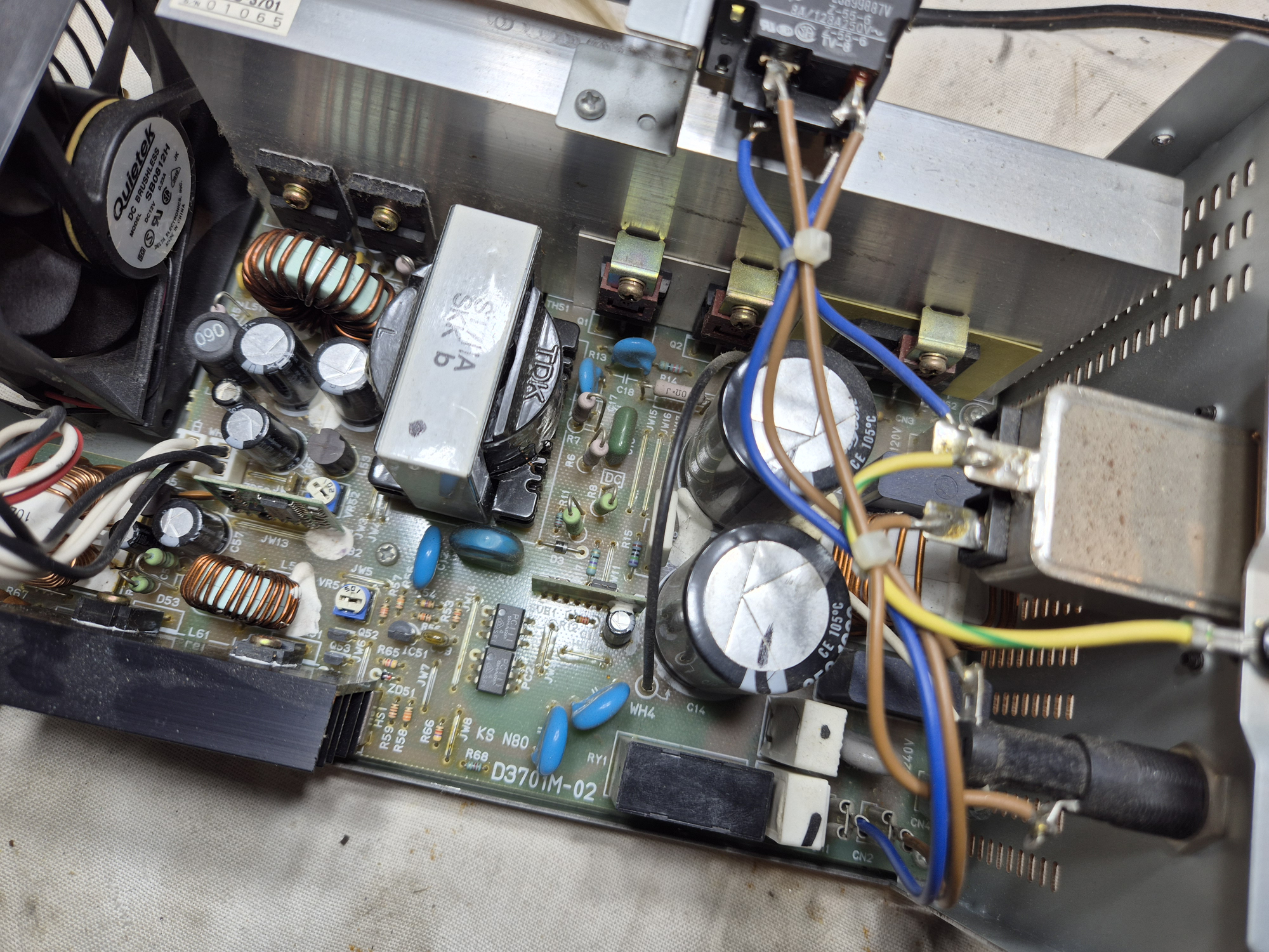
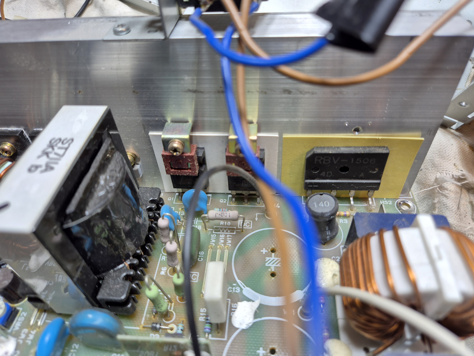
So, with the test meter on the caps there’s no volts anywhere so I’m thinking we’ve got an issue with the bridge rectifier as this is the heart of the PSU [or the heart of the first stage]. It’s the bridge rectifier matrix of 4 diodes that takes the AC and converts it into DC. A quick online calculation with the aid of ChatGPT revealed that I should be seeing around 320v DC on the caps in series or about 160v DC each.
I prefer to measure components out of circuit – you get much better and more reliable results. The bridge rectifier fitted to the IC-775 DPS is a 15A 600v 4 pin in-line unit. The part is a RBV-1506 which is now obsolete. The nice thing is that bridge rectifiers are not super fussy. As long as the amperage and voltage are within spec [or better] than the original, then you’re normally safe. Many modern bridges have better figures than their older counterparts.
On taking the component out and testing all 4 diodes in the matrix, I was noticing that something was not quite right between DC positive and DC negative. This should be 100% open circuit whichever direction you measure. I was getting 0.51v in reverse which says something was wrong. Potentially, this component was bad. A bad bridge normally means no DC.
I looked in the workshop and alas, no 4 pin inline bridges in the spares box. But coming to the rescue was a 50 Amp 1000v chunky replacement. I needed to mod the leads as this ‘big boy’ had spade connectors. The original was just 4 vertical pins.
Following on, I applied some heat sink compound to the rear of the new bridge and used the existing small M3 bolt [and a couple of oversize M4 washers] to successfully attach it to the heat sink and without doing any modifications.
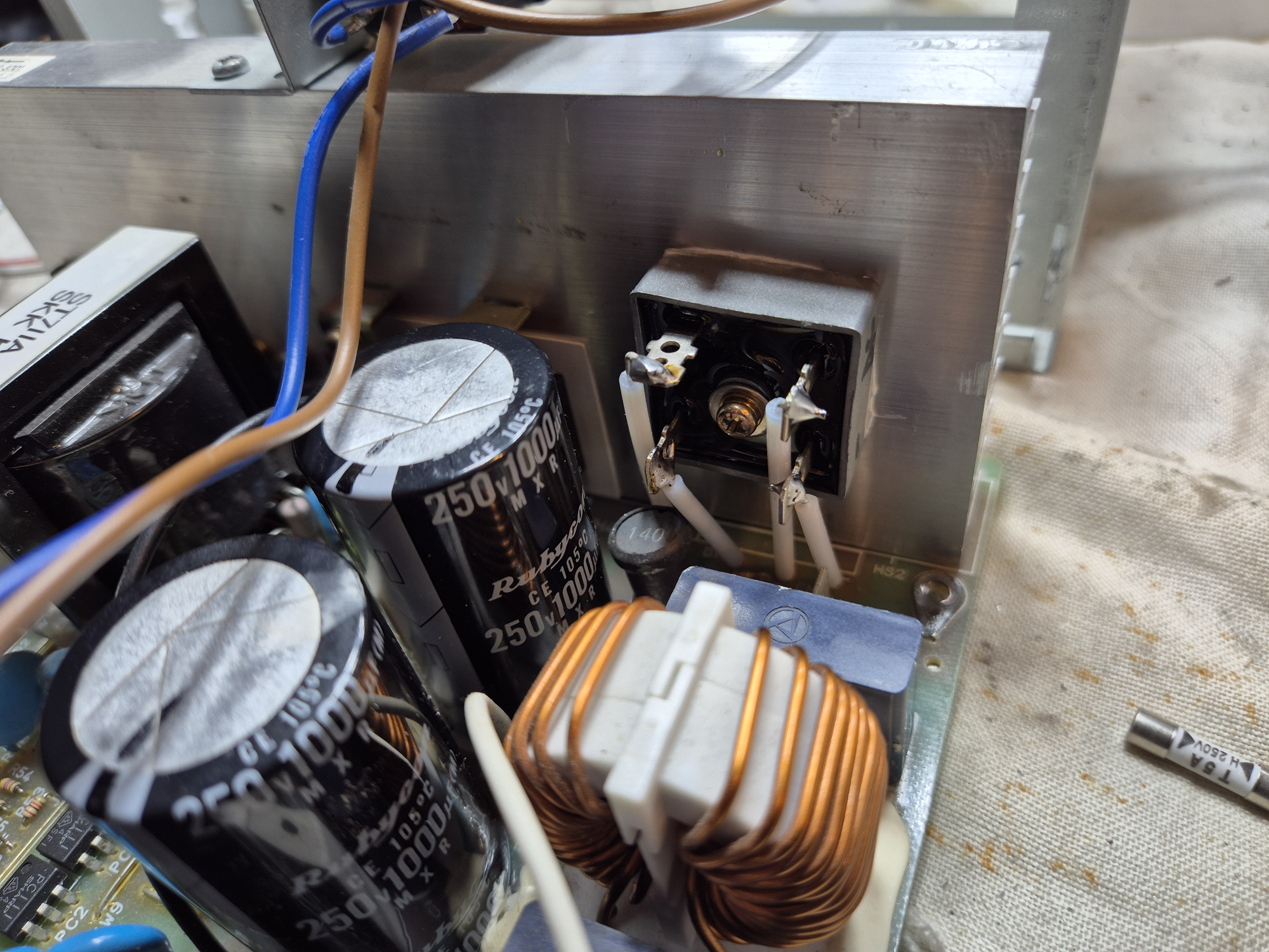
Silver coated wire from some old RG-142 coax off-cuts with PTFE insulation with the wires pushed through the vacant holes
The only mod needed then was to wire the spade terminals to the PCB using the through holes. I found a small off-cut of RG142 coax so used the silver plated inner conductor with the PTFE sleeve which gave it excellent isolation against nay possible short circuits.
So, time to test. Let’s see if we are getting any volts. On switch on there’s now a distinct ‘Click’ as the onboard relay energises. This is a good sign. I’ve wired two temporary leads on the underside where each electrolytic capacitor goes into the board. These wires go to my DMM which shows a very healthy 335v DC on the caps. This is much more encouraging.
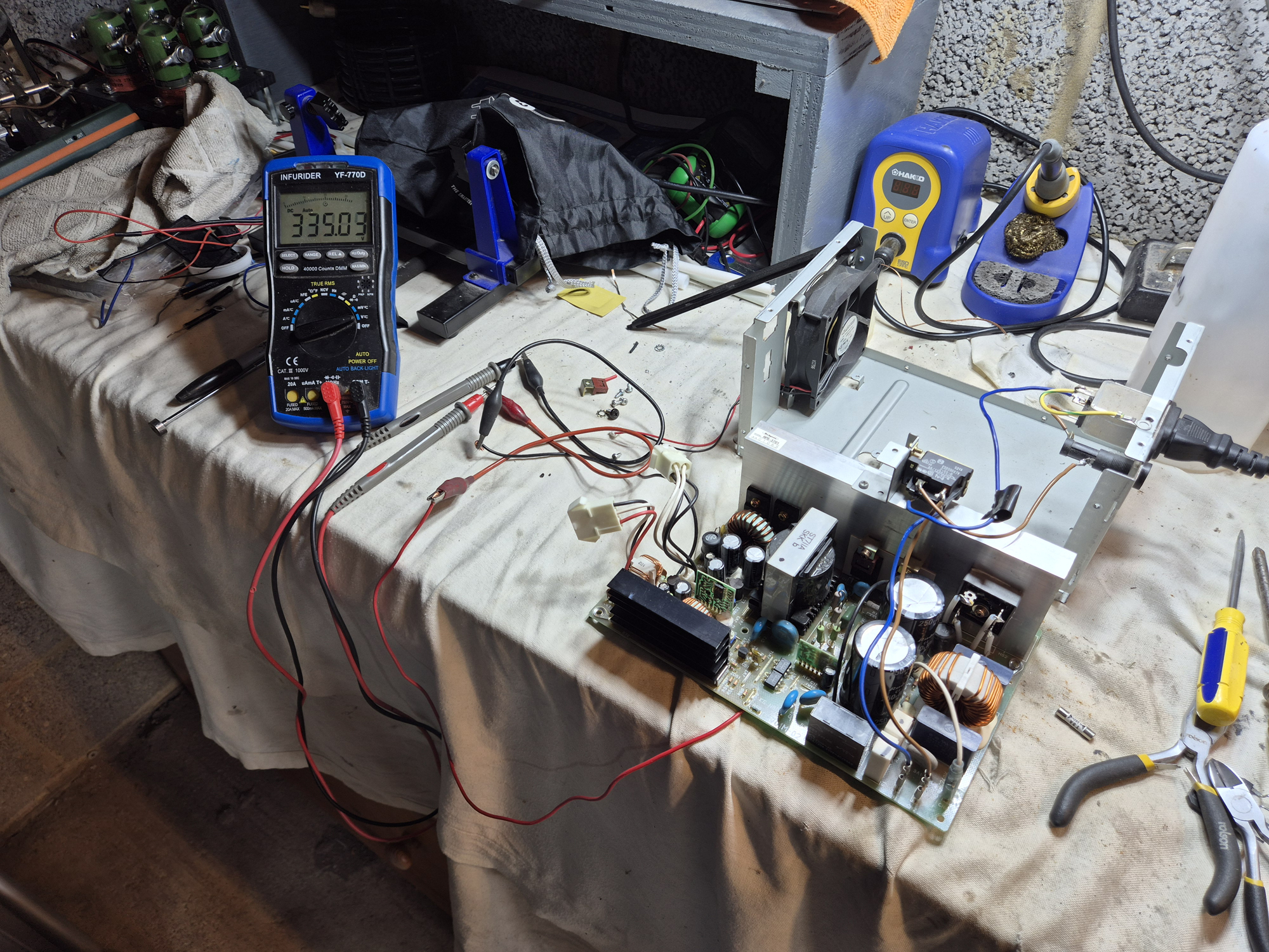
Now let’s check the outputs. We should have 28v on the outputs to the PA and 13.8v on the outputs to the front panel controls. Yes, both of these are showing good. In all, a great result. A bad bridge rectifier was the culprit. Welcome the IC-775 DSP back to life. It took a few hours – not a year.